Manual
numgeo-GiD, September 2026
numgeo-GiD is the graphical user interface for numgeo, a finite element program for geotechnical engineering.
numgeo solves boundary value problems in soil and rock. Soil can be treated as a single-phase solid, as a saturated two-phase medium in which the deformation of the soil skeleton and the flow of pore water are solved together, or as an unsaturated three-phase medium with pore air. It offers a wide range of constitutive models for sand and clay, contact between bodies, embedded structural members, and calculation procedures for geostatic, static, transient, dynamic and strength-reduction analyses.
The numgeo-GiD problemtype integrates numgeo into the GiD pre- and post-processor, so that geometry creation, meshing, model definition, running the simulation and the visualisation of the results, all can be done in one place.
This manual describes the interface: what each part of the workspace does, how the model data is organised, and how a model is built — assigning element types and materials, defining interactions, loads, initial conditions and calculation steps. The meaning of the quantities being defined — element formulations, constitutive models, step procedures, boundary conditions, output — is described in the numgeo reference manual, which this manual links to throughout rather than repeating.
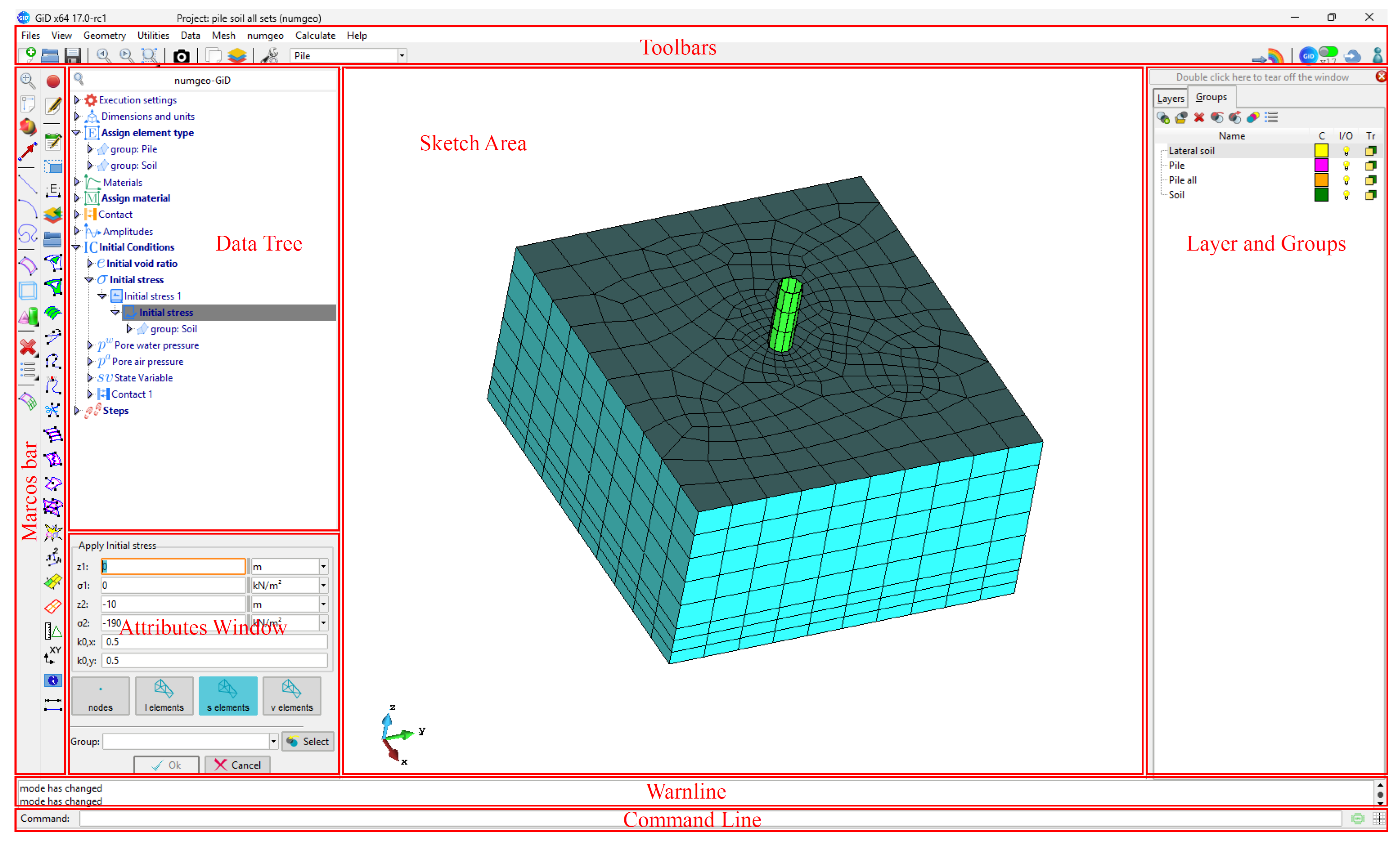
The workspace
The figure above shows the numgeo-GiD workspace as it appears after the problemtype is loaded. numgeo extends GiD's interface rather than replacing it: the parts it adds are the numgeo toolbar, the data tree and the visualisation panel.
The regions are described below in the order in which they are labelled in the figure.
Toolbars
Three toolbars are visible in the figure: the standard toolbar along the top, and two vertical toolbars at the left. The first vertical toolbar is GiD's; the second is added by numgeo.
Standard toolbar
The row along the top is used for creating, opening and saving projects, for undo and redo, for view control and image capture, and for showing and hiding the layers and groups windows.
The drop-down list at its right end selects the layer in which newly created geometry is placed.
GiD macros toolbar
The first vertical toolbar holds the commands for building and meshing the model: points, lines, surfaces and volumes, and the operations that act on them. The geometry of the model is created here.
numgeo toolbar
The second vertical toolbar is the main entry point for defining the model. Its buttons are grouped in the order in which a model is usually built.
Generators
| Button | Purpose | |
|---|---|---|
 |
Pile generator | Generate a 3D monopile or a 2D axisymmetric pile together with the surrounding soil |
 |
Embedded anchor / pile generator | Generate embedded anchors or piles inside a host region |
Model properties
| Button | Purpose | |
|---|---|---|
 |
Material manager | Define continuum materials and their constitutive models |
 |
Truss/beam material manager | Define the sections and properties of truss and beam members |
 |
Interaction manager | Define contact interactions |
Loading
| Button | Purpose | |
|---|---|---|
 |
Amplitude manager | Define amplitudes |
 |
Load manager | Define loads |
 |
Initial-condition manager | Define initial conditions |
Checking
| Button | Purpose | |
|---|---|---|
 |
Model visualisation | Draw the conditions of the model on the geometry |
Calculation
| Button | Purpose | |
|---|---|---|
 |
Step manager | Define the calculation steps |
 |
Input files | Create, view and edit the numgeo input files |
 |
Process monitor | Start the calculation and follow its progress |
 |
ParaView | Open the results in ParaView |
The topmost button carries the numgeo logo and is a label for the bar rather than a command.
If the toolbar is not visible it can be restored from GiD's toolbar settings, where it is registered as numgeo tools toolbar.
Data tree
The data tree holds the part of the model definition that is attached to geometric entities. Where a manager defines what something is, the tree records where it applies.
A branch is expanded with the triangle to its left. Five branches are shown:
| Branch | Holds | |
|---|---|---|
 |
Assign element type | The element formulation and integration scheme |
 |
Assign material | The material given to each part of the model |
 |
Embedded region | Members constrained to follow a surrounding host |
 |
Assign contact | Contact pairs and their interactions |
 |
Steps | The calculation steps |
Sketch area
The sketch area is where the model is displayed and picked: the geometry, the mesh, and the symbols drawn for loads, boundary conditions and initial conditions. The triad at the lower left shows the orientation of the global axes.
Visualisation panel
A small floating panel sits above the sketch area. It shows what has been assigned and to which part of the model, and it works together with the model visualisation in the numgeo toolbar: the panel gives permanent access to the drawing without opening the full viewer.
- The eye button turns symbol drawing on and off.
- The contact button highlights the contact pairs.
- The step selector chooses which conditions are drawn. With No step (initial / embedded only) the model-wide initial conditions are shown together with the active embedded anchors, beams and piles. With a calculation step selected, the initial conditions are hidden and the conditions supported in that step are shown instead, together with the embedded members that persist through it.
Symbols are drawn on request rather than automatically.
Layers and groups windows
This is GiD's standard mechanism for organising a model into parts, and it is where the parts of a model are separated from one another.
Layers control visibility and colour, and each entity belongs to one layer. Groups are named collections of entities.
Status bar
The line under the sketch area reports what GiD is doing: the file being saved, the result of the last command, and warnings.
Command line
Commands and coordinates can be typed here instead of being picked with the mouse.
Typical workflow
A model is usually built in the following order. Steps 3 to 7 can be done in any order.
- Create the geometry in GiD, or with the generators.
- Set the problem dimensions.
- Define the materials in the material manager and the truss/beam material manager.
- Assign element types and materials through the data tree.
- Define the interactions — contact pairs and embedded regions.
- Define the amplitudes, then the loads, boundary conditions and initial conditions.
- Define the calculation steps.
- Generate the mesh with GiD's meshing tools.
- Start the calculation.
- Visualise the results.