Muskat problem
Development of geometry model and groups
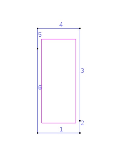
Creating a geometry is the first step to run a problem in numgeo with GiD. The shape can be made by using the straight line ![]() and entering exact coordinates into the command line. Following are the cordinates for the muskat problem:
and entering exact coordinates into the command line. Following are the cordinates for the muskat problem:
0,0
0,3.22
0,4
1.62,4
1.62,0.48
1.62,0
After entering all coordinates, close the shape by clicking on the first point to join it. Then, define the NURBS surface by selecting all the lines and press ‘Esc’ to finish.
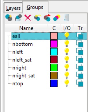
Add all relevant groups using the tab on the right side. For the groups nleft, nleft_sat, nright, nright_sat, ntop, and nbottom, select the corresponding lines. For the group eall, select the entire surface.
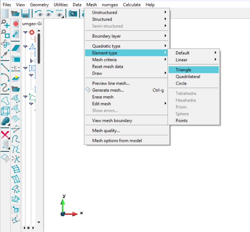
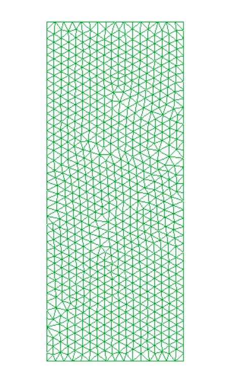
Next, the mesh was generated. The element type can be triangular or quadrilateral; in this simulation, a triangular mesh element was used. The mesh was created with an element size of 0.1 m. For improved visualization, the mesh view was toggled using the button ![]() on the left toolbar.
on the left toolbar.
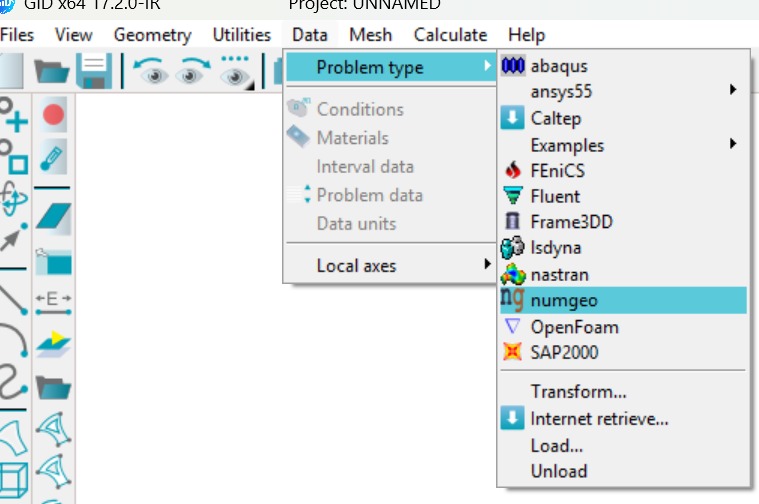
To define the model properties, first load the numgeo problem type in GiD by navigating to Data → Problem type → numgeo. A data tree will appear on the left hand side of the screen.
Set the problem dimension to 2D (Plane strain), and assign element 3-phase u-p stabilized formulation with full integration to soil_all, which enables the simultaneous consideration of soil, water, and air phases.

Materials properties
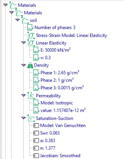
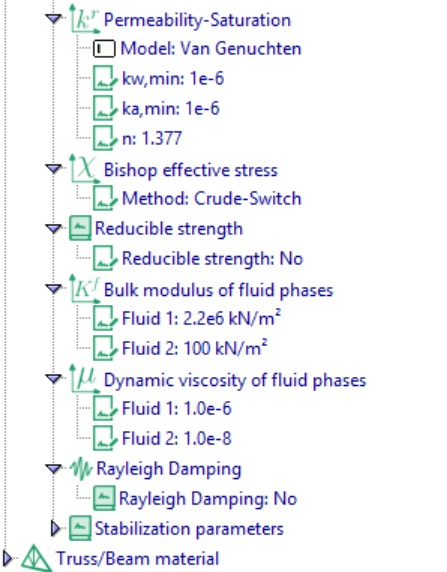
Next, we define the material properties. Under Material Definition, create a material named “mat_subsoil” and specify its parameters, including the number of phases, stress–strain model, density, permeability, saturation–suction relationship, permeability–saturation relationship, Bishop’s effective stress, bulk modulus, and dynamic viscosity, as shown in Figure 8.
Assign materials
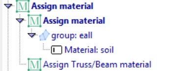
Next, we assign the materials. This step involves specifying the defined material properties to the corresponding section.
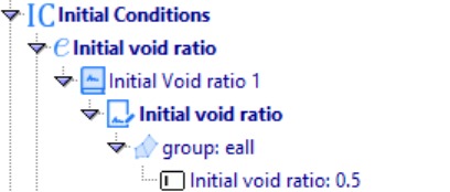
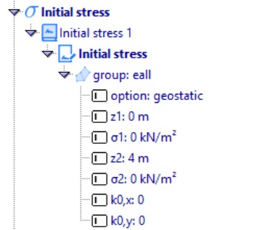
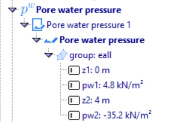
Initial conditions
The next step is to define the initial conditions for the numerical model.
Simulation steps
Step 1: Geostatic
The next step is to define the geostatic step for the dam model. This step applies gravity loading to account for the self-weight of the dam materials, ensuring a realistic initial stress state before applying transient reservoir loads. Set the analysis type to Geostatic and specify the increment as 1.