Grouted anchor generator
The anchor generator creates grouted anchors inside an existing soil mesh. One definition describes the anchor — its lengths, its orientation, its materials and its interface — and that definition can then be placed at as many head locations as the model needs.
An anchor is built from two members: a tendon, modelled as a truss, running free from the head, and a grout body, modelled as a beam, bonded to the soil at the far end. Only the grout body is coupled to the host; the free tendon length transmits force without interacting with the soil around it.
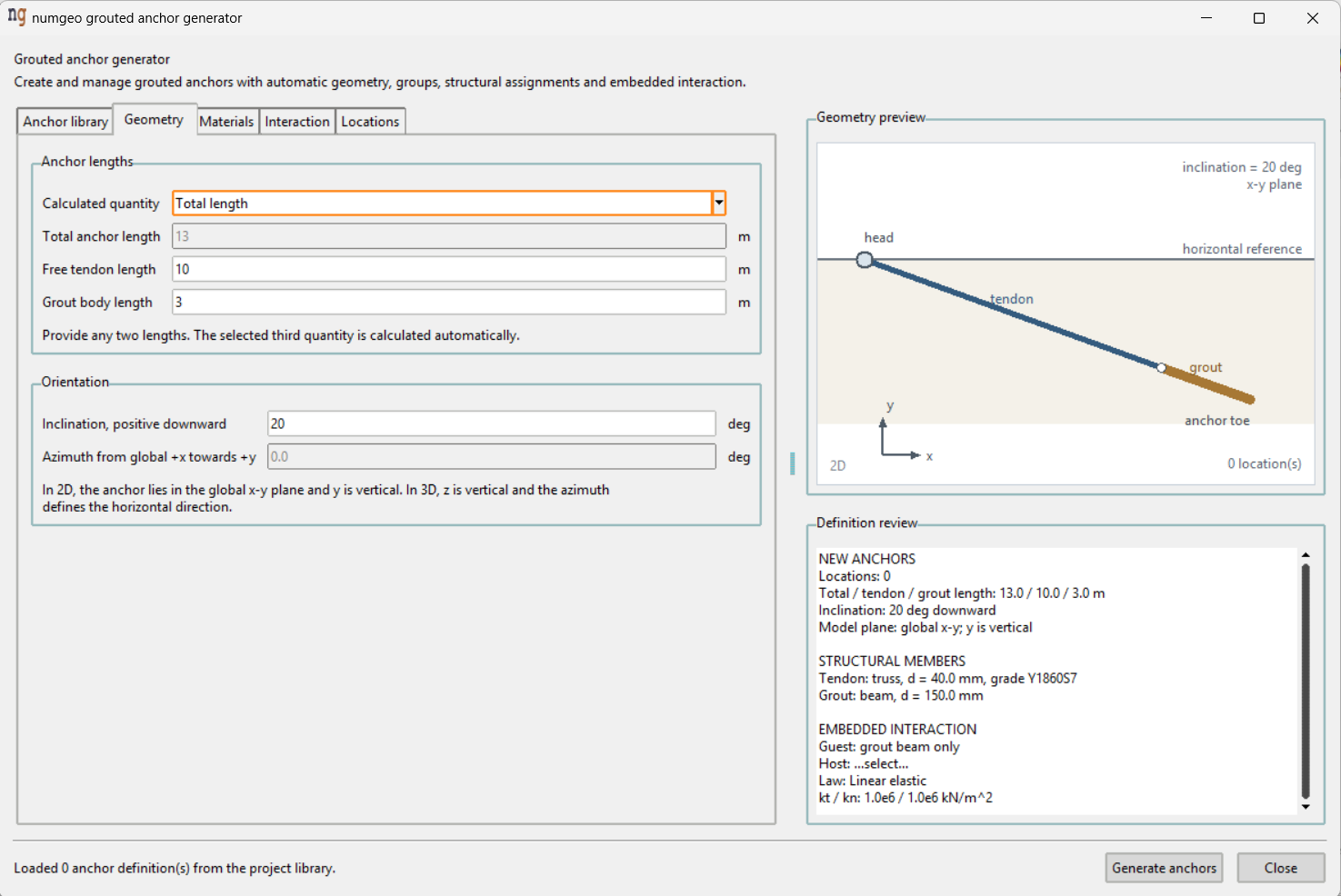
The window is organised as a library of definitions with five tabs, a geometry preview and a definition review.
Anchor library
The library lists the anchor definitions in the project.
| Button | Action |
|---|---|
| New definition | Create an anchor definition |
| Edit selected | Load the selected definition into the tabs |
| Activate / deactivate | Switch a definition in or out of the model |
| Delete selected | Remove the definition |
| Reload | Reread the library from disk |
Activate / deactivate is the useful one for staged analyses. An inactive anchor keeps its geometry and its groups, but loses its element type, material assignments and embedded interaction — so the member is still there to be switched back on, without contributing to the calculation meanwhile.
Geometry
| Field | Unit | Default |
|---|---|---|
| Total anchor length | m | 15.0 |
| Free tendon length | m | 5.0 |
| Grout body length | m | 10.0 |
| Inclination, positive downward | deg | 15.0 |
| Azimuth from global +x towards +y | deg | 0.0 |
The three lengths are not independent. Calculated quantity selects which one is derived — total length, tendon length or grout length — and the other two are entered. Give any two and the third follows.
Orientation depends on the dimension of the model. In 2D the anchor lies in the global x–y plane with y vertical, and only the inclination applies. In 3D, z is vertical and the azimuth rotates the anchor about it, measured from the global +x axis towards +y.
Inclination is positive downward, so a ground anchor raking into a slope takes a positive value.
Materials
Two sets of properties, one per member.
Grout body — beam
| Field | Unit | Default |
|---|---|---|
| Diameter | mm | 150.0 |
| Young's modulus | GPa | 20.0 |
| Poisson's ratio | – | 0.20 |
| Density | g/cm³ | 2.20 |
Shear correction factor κ |
– | 0.90 |
Tendon — truss
| Field | Unit | Default |
|---|---|---|
| Steel grade / preset | Y1860S7 |
|
| Equivalent diameter | mm | 40.0 |
| Young's modulus | GPa | 195.0 |
| Density | g/cm³ | 7.81 |
Steel grade offers Custom, S235, S355, Y1770S7 and Y1860S7. The
two Y grades are prestressing strand; S235 and S355 are structural steel.
Choosing a preset supplies the elastic modulus and the density; Custom leaves
them editable.
The equivalent diameter defines the truss area. For a multi-strand tendon it is the diameter of a single bar with the same cross-sectional area as the strands together, not the diameter of the borehole or of one strand.
Interaction
Create embedded interaction for each grout body is on by default. With it off, the anchor is generated as geometry and groups only, with no coupling to the soil.
Host continuum group selects the soil region the grout body is embedded in, from the groups in the model. Refresh rereads them after groups have been added or renamed.
Axial law describes the interface along the grout body:
| Law | Parameters |
|---|---|
| Linear elastic | kt, kn |
| Constant | kt, kn, ultimate axial traction tult |
| Mohr-Coulomb | kt, kn, cohesion, friction angle, shear surface per unit length As |
Defaults are kt and kn of 1.0e6, tult of 100.0, cohesion 100.0 and
friction angle 25°.
As is the shear surface per unit length of the grout body, in metres — the
circumference over which the interface transmits shear. It is computed from the
grout diameter unless overridden.
Note
Only the grout body is coupled to the host. The free tendon segment stays uncoupled, which is what distinguishes a ground anchor from a fully bonded bar: the load is carried past the active zone and transferred to the soil only at the far end.
Locations
One definition, many anchors. The Locations tab holds a list of head coordinates, and the anchor is generated at each of them with the same geometry, materials and interface.
| Button | Action |
|---|---|
| Add location | Add the entered coordinate to the list |
| Update selected | Overwrite the selected coordinate |
| Duplicate selected | Copy the selected coordinate |
| Remove selected | Delete it from the list |
A row of anchors behind a retaining wall is one definition with one location per anchor, rather than a definition each.
Preview and review
The Geometry preview draws the anchor from the values entered, and the Definition review summarises what will be created. Both update as the tabs are edited, so a definition can be checked before it is generated.
Embedded members are described under Embedded regions in the numgeo reference manual.