3D monopile generator
The 3D monopile generator builds a complete model: a rectangular block of layered soil with a hollow or solid pile extruded through it. It creates the geometry, the layers and the groups in one action, so that materials, contact and boundary conditions can be assigned immediately afterwards.
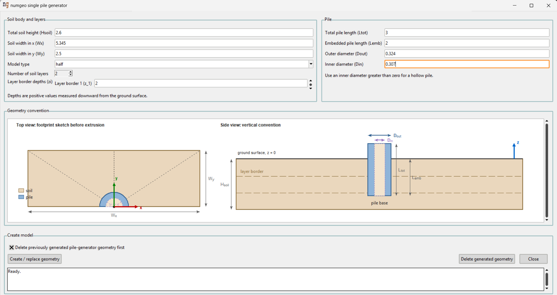
Soil body and layers
| Field | Meaning |
|---|---|
| Total soil height (Hsoil) | Depth of the soil block below the ground surface |
| Soil width in x (Wx) | Extent of the block in the x-direction |
| Soil width in y (Wy) | Extent of the block in the y-direction |
| Model type | half or full |
| Number of soil layers | How many layers the block is divided into |
| Layer border depths (zi) | The depth of each boundary between layers |
Model type decides whether the whole soil block is built or only half of it.
A half model exploits the symmetry of an axially or laterally loaded pile
about the x–z plane, halving the size of the mesh. It requires symmetry boundary
conditions on the cut face. Use full when the loading or the soil profile is
not symmetric.
Layer borders are given as depths, positive downwards from the ground surface, and one border field appears for each boundary — two layers need one border, three need two. With a single layer no border is required and the field says so.
The depths must lie between zero and the total soil height, and in increasing order.
Pile
| Field | Meaning |
|---|---|
| Total pile length (Ltot) | Full length of the pile, including the part above ground |
| Embedded pile length (Lemb) | Length below the ground surface |
| Outer diameter (Dout) | Outer diameter of the pile |
| Inner diameter (Din) | Inner diameter — leave at zero for a solid pile |
The difference between Ltot and Lemb is the free length standing above the
ground surface, which is where a lateral load or moment is applied on a
monopile.
Inner diameter greater than zero produces a hollow pile with a wall
thickness of (Dout − Din) / 2, which is how an open-ended tubular monopile is
modelled. The soil inside the hollow section is generated as its own body — the
soil plug — so it can be given its own material and can move relative to the
pile.
Lemb must not exceed Ltot, and Din must be smaller than Dout.
Geometry convention
The two sketches in the middle of the window are drawn from the values entered and update as they change. They are the quickest way to confirm that a model is what was intended before generating it.
Top view shows the footprint before extrusion, with the pile at the origin
and the x and y axes marked. In a half model the sketch shows the half block,
so the symmetry plane is visible.
Side view shows the vertical convention: the ground surface at z = 0, the
layer borders as dashed lines, and Ltot, Lemb, Dout and Din marked
against the pile.
Note the sign convention. The z-axis points upward, so soil is at negative z, but the layer border depths are entered as positive numbers measured downward.
Creating the model
Create / replace geometry generates the model. Delete previously generated pile-generator geometry first is ticked by default and clears the previous result, which is what makes it safe to adjust a value and generate again.
Delete generated geometry removes what the generator made without creating anything new.
The message area at the bottom reports progress and any problem encountered.
Warning
Both delete actions remove only geometry the generator created — anything in
the numgeo_pilegen_soil and numgeo_pilegen_pile layers. Geometry drawn by
hand in other layers is untouched, but material assignments and conditions
attached to the deleted geometry are lost with it. Regenerate before
assigning, not after.
What is generated
The generator creates two layers, numgeo_pilegen_soil and
numgeo_pilegen_pile, and a set of named groups ready for assignment:
| Group | Contains |
|---|---|
soil |
The soil body |
pile |
The pile |
layer_01, layer_02, … |
One group per soil layer, for assigning different materials |
soil-plug |
The soil inside a hollow pile |
surf-pile-top |
The top face of the pile, where load is applied |
surf-pile-base |
The base of the pile |
surf-pile-shaft-outside |
The outer shaft surface, for contact with the soil |
surf-pile-shaft-inside |
The inner shaft surface, for contact with the soil plug |
surf-soil-top |
The ground surface |
surf-soil-base |
The bottom of the soil block |
surf-soil-outside |
The outer vertical faces of the block |
surf-soil-sides-x, surf-soil-sides-y |
The individual side faces, for boundary conditions |
Note
These groups are a starting point, not a limit. Further groups can be created in the Layers and groups window for anything the model needs — a set of nodes along a drainage boundary, a region of soil to be excavated in a later step, the nodes where a displacement is monitored. The generated groups can also be edited: entities can be added to them or removed from them like any other group.
The layer groups are what make a layered profile straightforward: assign a
different material to each in the
Assign material branch. The
shaft surfaces are the master and slave groups of a
contact pair, and in a half model the
symmetry conditions go on the appropriate surf-soil-sides group.