Load manager
In a multi-step analysis the same load often has to be adjusted step by step — a pressure increased, a force reversed, a load removed once excavation begins. Doing this through the data tree means opening each step in turn. The load manager shows every load assignment of a step in one table and edits them in place, with the option of carrying a change forward into the following steps.
Open the manager with the  button in the numgeo toolbar, or from numgeo → Manager → Load.
Important
The load manager edits existing load assignments. Creating a new load — assigning a load type to a geometric entity for the first time — is still done in the data tree, under the step concerned. Once the assignment exists, the manager takes over.
Window layout
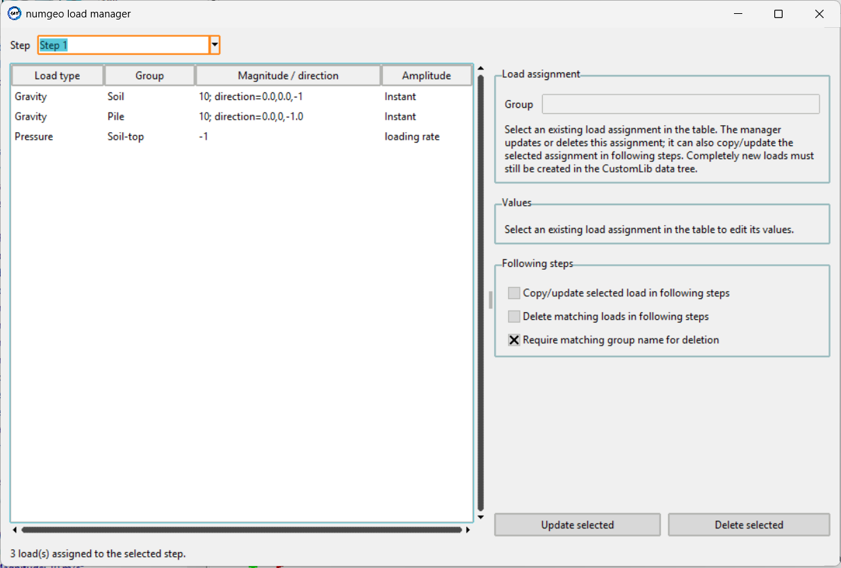
The Step selector at the top determines which step is shown. All editing applies to that step, and to later steps only if propagation is switched on. The line at the bottom of the window reports how many loads the selected step carries.
The table on the left lists the load assignments of that step:
| Column | Content |
|---|---|
| Load type | The kind of load |
| Group | The entity group the load is assigned to |
| Magnitude / direction | The current values, summarised |
| Amplitude | The amplitude driving the load |
The Load assignment panel on the right names the group of the selected row, and the Values panel below holds the fields for that load type. The fields follow the type, so a pressure shows a single magnitude while a point load shows components per direction. A load type that carries no scalar values says so rather than showing an empty form. With nothing selected, both panels prompt you to pick a row.
Update selected writes the edited values back, and Delete selected removes the assignment.
Load types
The load types that can appear in the table are those defined in the data tree:
| Load type | Applies to |
|---|---|
| Gravity | Surfaces, volumes |
| Point load | Points |
| Pressure | Lines, surfaces |
| Water Pressure | Lines, surfaces |
| Drainage | Lines, surfaces |
| Ground springs (Winkler) | See below |
| Compliant base | Lines, surfaces |
| Inflow/Outflow | Lines, surfaces |
| Mass point | Points, lines |
| Spring-damper element | Two node sets |
Water Pressure calculates the surface pressure itself, from the pore water pressure at the surface nodes, rather than taking a magnitude.
Ground springs (Winkler) covers three separate conditions, chosen by what they act on: normal/tangential on 2D solid edges, global X/Y/Z on 3D solid faces, and global X/Y/Z on beam elements.
Warning
The Winkler spring stiffness k is a stiffness density, integrated over
the element, so its unit depends on the element type. Check it against a
single-element patch test before relying on it in a full model.
Following steps
Three checkboxes at the bottom of the editor control whether a change reaches beyond the selected step. All propagation is opt-in, so that nothing is altered in a later step by accident.
Copy/update selected load in following steps — applies the edited values to every following step. If the load does not exist in a later step, it is created there. This is the option to use when a load has been defined once and should now hold at a new value for the rest of the analysis.
Delete matching loads in following steps — removes the corresponding assignment from every following step as well, rather than only from the selected one.
Require matching group name for deletion — narrows what counts as "matching". Enabled by default. With it on, a load in a later step is deleted only if both its type and its group agree with the selected row. Switching it off makes deletion match on the load type alone, which will remove that load type from every group in the following steps.
Warning
Turning off group matching is the one setting here that can remove more than expected. With it off, deleting a pressure on one surface deletes the pressure on every surface in all following steps.
Typical use
Changing a value for the rest of the analysis — select the step where the change begins, edit the value, tick Copy/update selected load in following steps, then Update selected.
Removing a load from a certain step onwards — select the step, select the row, tick Delete matching loads in following steps, then Delete selected.
Correcting a single step — leave both propagation boxes unticked and edit normally.
Because the manager works directly on the data tree, every change is immediately visible there and in the visualisation panel.
Loads are described under Loads in the numgeo reference manual.