Embedded pile generator
The embedded pile generator creates 3D beam piles inside an existing soil mesh. The pile is a line of beam elements, and the soil around it is coupled to that line through an implicit interaction surface — a cylinder of the given diameter that exists numerically without being meshed.
This is what makes a pile group tractable. Meshing twenty piles and their interfaces explicitly is expensive; embedding twenty beam lines in a soil mesh that was generated without them is not.
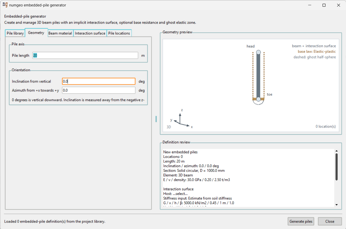
Like the anchor generator, this one keeps a library of definitions and places each at as many locations as needed. Five tabs, with a geometry preview and a definition review beside them, and Generate piles at the bottom.
Pile library
Definitions stored with the project. They can be created, edited, activated or deactivated, and deleted, in the same way as anchor definitions.
Geometry
| Field | Unit | Default |
|---|---|---|
| Pile length | m | 20.0 |
| Inclination from vertical | deg | 0.0 |
| Azimuth from +x towards +y | deg | 0.0 |
Zero inclination is vertically downward, measured away from the negative z-axis, so a raking pile takes a positive inclination and an azimuth setting the direction it leans in.
Beam material
Circular pile section
| Field | Unit | Default |
|---|---|---|
| Section type | Solid circular |
|
| Outer diameter | mm | 1000.0 |
| Wall thickness | mm | 50.0 |
Wall thickness applies to a hollow section and is ignored for a solid one.
Pile beam properties
| Field | Unit | Default |
|---|---|---|
| Young's modulus | GPa | 30.0 |
| Poisson's ratio | – | 0.20 |
| Density | t/m³ | 2.50 |
| Shear correction factor | – | 0.90 |
The section properties of the beam — area, second moments, torsional constant — are computed from the diameter and wall thickness, so they are not entered.
Interaction surface
The largest tab, and the one that decides how the pile transfers load to the soil.
Host region selects the soil group the pile is embedded in.
Shaft stiffness
Stiffness input offers two ways of arriving at the interface stiffnesses:
| Mode | What is entered |
|---|---|
| Direct | kt, kn and kb in kN/m³ |
| Estimate from soil stiffness | Soil properties, from which the stiffnesses are computed |
The estimate mode is the more useful of the two, because interface stiffnesses are hard to judge directly while soil stiffness is not:
| Field | Unit | Default |
|---|---|---|
| Operational soil shear modulus, G | kN/m² | 5000.0 |
| Operational soil Young's modulus, E | kN/m² | 14500.0 |
| Soil Poisson's ratio, ν | – | 0.45 |
| Characteristic host element size, h | m | 1.0 |
Either G or E is given, selected by modulus input; the other follows from
the Poisson's ratio.
Characteristic host element size is the size of the soil elements the pile passes through. It matters because the interface stiffness has to be scaled to the mesh it acts on — the same physical interface needs a different numerical stiffness in a coarse mesh than in a fine one. It can be determined automatically from the host mesh.
Three scaling factors — Nt, Nn and Nb, all defaulting to 1.0 — adjust
the tangential, normal and base stiffnesses individually, and an advanced
near-field thickness factor β adjusts the zone over which the interface acts.
The Computed stiffnesses box shows the resulting kt, kn and kb, so the
effect of each change is visible immediately.
Shaft capacity
Shaft law is Constant or Mohr-Coulomb.
| Field | Unit | Default | Used by |
|---|---|---|---|
Constant shaft capacity, tult |
kN/m² | 100.0 |
Constant |
| Interface cohesion | kN/m² | 5.0 |
Mohr-Coulomb |
| Interface friction angle | deg | 27.5 |
Mohr-Coulomb |
With Mohr-Coulomb the capacity follows the pressure at the shaft, and three further settings decide how that pressure is obtained:
- Capacity-pressure source —
InterfaceorSoil. - Soil-stress recovery —
Inverse-distanceorGaussian. The Gaussian option adds a support factor, defaulting to1.0. - Maximum capacity pressure
p_max— optional, defaulting to1000.0kN/m², capping the pressure the capacity is derived from.
Base resistance
On by default, and disabled for a pile that carries load through the shaft alone.
| Field | Unit | Default |
|---|---|---|
Base stiffness, kb |
kN/m³ | 50000.0 |
Compressive base capacity, σ_lim |
kN/m² | 5000.0 |
| Base mobilisation | Elastic-plastic |
|
Hyperbolic capacity scaling, f |
– | 1.0 |
Base mobilisation is Elastic-plastic or hyperbolic. The elastic-plastic law
mobilises the base linearly until the capacity is reached; the hyperbolic law
approaches it gradually, which matches measured load–settlement behaviour more
closely. The scaling factor applies to the hyperbolic law only.
The base acts as a physical disk at the toe rather than as a point, which is why it needs its own quadrature setting below.
Ghost elastic zone
On by default, with a Young's modulus of 75000.0 kN/m² and a Poisson's ratio
of 0.30.
The pile occupies space that the soil mesh also occupies, since the two are not meshed around one another. The ghost zone replaces the soil inside the pile diameter with a stiff elastic material, so those host elements are not distorted by carrying both the pile and the soil at once. In the preview it is drawn as a dashed half-sphere at the toe.
Numerical settings
| Field | Default | Meaning |
|---|---|---|
Circumferential points per ring, np |
8 |
How finely the shaft surface is sampled around its circumference |
| Base-disk quadrature points | 9 |
How finely the base disk is integrated |
Raising either improves the resolution of the coupling at the cost of calculation time. The defaults are adequate for most models.
Pile locations
A list of pile-head coordinates. The definition is generated at each one, so a pile group is one definition with one location per pile.
Preview and review
The Geometry preview draws the pile with its interaction surface, marking the head and the toe, and names the base law and the ghost zone. The Definition review beside it is a written summary of everything that will be created — lengths, section, material, host, stiffness mode and computed values.
Reading the review before pressing Generate piles is the quickest check that
a definition is what was intended, particularly the host group, which reads
...select... until one is chosen.
Embedded members are described under Embedded regions in the numgeo reference manual.