Truss/beam material manager
Truss and beam elements are one-dimensional structural members, and their material definition consists of a stiffness together with section properties rather than a constitutive model. They therefore have their own manager, separate from the material manager.
Open the manager with the  button in the numgeo toolbar, from numgeo → Manager → Truss/Beam material,
or from the Assign material
branch of the data tree when picking a section for a line.
button in the numgeo toolbar, from numgeo → Manager → Truss/Beam material,
or from the Assign material
branch of the data tree when picking a section for a line.
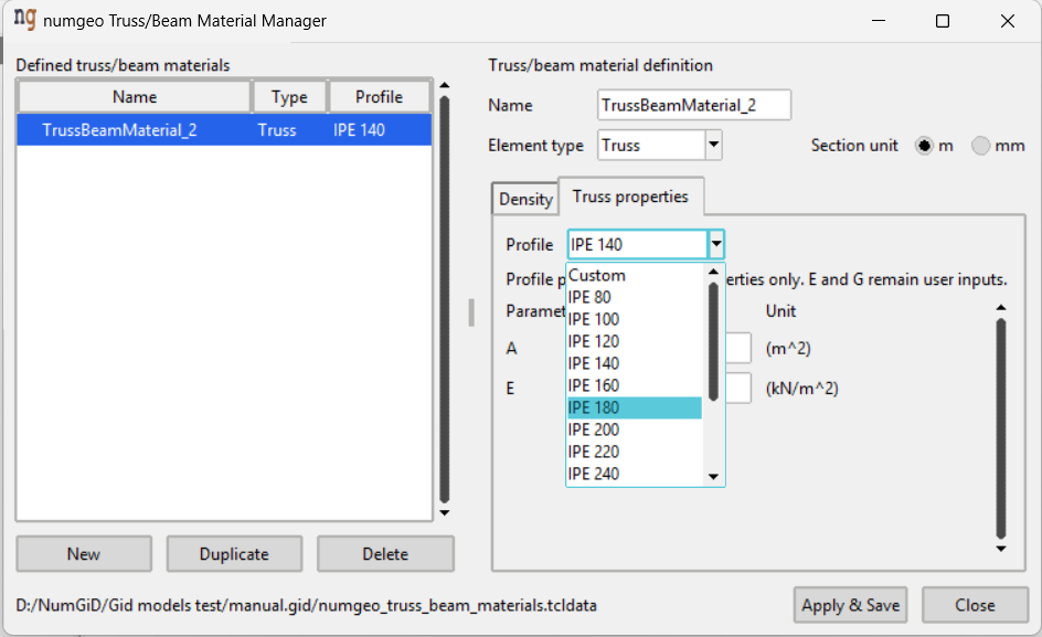
The window works like the continuum material manager — the same list on the left with New, Duplicate and Delete underneath, and Apply & Save and Close at the bottom right. Use selected material appears when the manager was opened from the data tree in order to pick a section.
The Defined truss/beam materials list shows each material with its element type and the profile it was built from.
Element type
Each material is either a Truss or a Beam, chosen from the drop-down beside the name. The choice determines which section properties are asked for: the second tab is renamed accordingly, and its table is rebuilt immediately.
| Type | Carries | Properties |
|---|---|---|
| Truss | Axial force only | Truss properties |
| Beam | Axial force, bending, shear and torsion | Beam properties |
Section unit
Section properties can be entered in either m or mm, chosen with the radio buttons at the right of the element type. The setting is stored with the material, so different materials in the same project may use different units.
Choose the unit before typing the values, or before applying a profile.
Note
The section unit governs how the values you type are read. Changing it does not convert what is already in the table, so make sure every value in a material is entered in the same unit as the one selected. Mixing metres and millimetres in one section gives a member that is orders of magnitude too stiff or too soft, and nothing in the manager will point it out.
Density
A single density for the member, in g/cm³.
Profile
Rather than typing section properties by hand, they can be filled from a catalogue of rolled-steel IPE profiles, selected from the Profile list at the top of the properties tab:
| IPE 80 | IPE 180 | IPE 300 | IPE 400 |
| IPE 100 | IPE 200 | IPE 330 | IPE 450 |
| IPE 120 | IPE 220 | IPE 360 | |
| IPE 140 | IPE 240 | ||
| IPE 160 | IPE 270 |
A profile fills the section properties only, converted to the section unit
currently selected. E, G, the shear correction factors and the density
describe the material rather than the geometry of the section and remain your
inputs.
The filled values are ordinary numbers and can be edited afterwards. The selected profile is remembered with the material and shown in the Profile column of the list; a material whose properties were typed by hand is listed as Custom.
Validation
The material is checked when Apply & Save is pressed:
- The name must not contain commas or line breaks.
- The type must be Truss or Beam.
- The section unit must be m or mm.
- The density must be filled.
- Every parameter of the selected type must be filled.
A problem shows a warning naming it, and the material stays open so it can be corrected.