Truss frame
To validate the implementation of the truss elements, the truss frame depicted below is analysed.
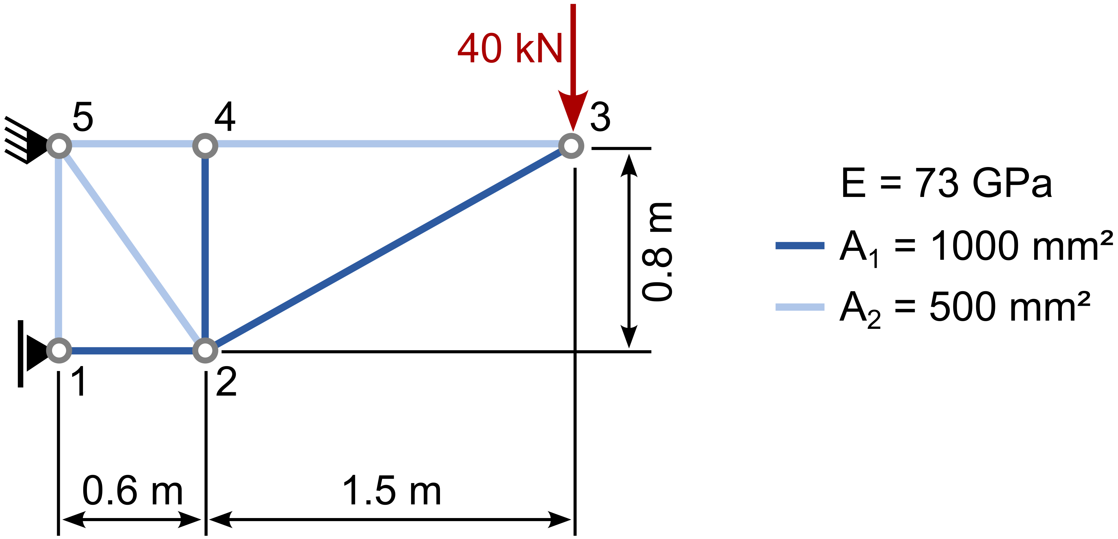
The members of the truss frame consist of sections of aluminum pipe with cross-sectional areas of \(A_1=1000\) mm² and \(A_2=500\) mm². The vertical deflection \(u_{y,3}\) at point 3 to be determined.
Analytical solution
Analytically \(u_{y,3}\) can be computed using the principle of work-energy, yielding a deflection of \(u_{y,3}^{analytical}=0.01627\) m.
Numerical solution
For the numerical solution 2-node linear truss elements are used. The Young's modulus and the cross-sectional areas are prescribed using the *Truss properties keyword of the *Material definition:
*Material, name = truss1, phases=1
*Truss properties
0.001, 73d6

*Material, name = truss2, phases=1
*Truss properties
0.0005, 73d6
Input files
The complete input files can be downloaded here
Results
The results of the numerical simulation are depicted below. The computed vertical displacement at node 3, which corresponds to the maximal displacement, is 0.01627 m and thus in perfect agreement with the analytical solution.
