Hertzian contact problem
Hertzian contact problem in 2D
In order to validate the implementation of the contact algorithms for the contact constraints in normal direction, the Hertzian contact problem is studied. In addition to the segment-based method, the element-based mortar method implemented in numgeo is considered.
The figure below shows the adopted mesh and the material properties (Young's modulus \(E\) and Poisson's ratio \(\nu\)) of the deformable bodies. The upper sphere (radius \(R=8\) m) is loaded by an uniform vertical traction which is equivalent to a force of \(F=10\) kN when integrated over the diameter. An irregular meshing with reciprocal non-aligned surface nodes is used in order to better identify the differences between the contact discretisation techniques. The lower sphere (radius \(R=8\) m) has exactly two times larger element edges at the surface in the symmetry axis compared to the upper sphere.
 Figure 1. Model of the two spheres for the 2D plain strain analyses
Tip
The input files for the 2D benchmark simulations can be downloaded here.
Normal contact stress vs. the horizontal coordinate starting from the symmetry axis of the model for the analytical solution based on the Hertzian contact theory and the simulations using the element-based and segment-based mortar methods implemented in numgeo is given below. A good accordance is observed. In addition, two simulations using triangular elements are evaluated. Either perfectly conforming meshes or non conforming meshes, where the lower sphere has exactly two times larger element edges at the surface in the symmetry axis compared to the upper sphere, are used.
 Figure 2. Results for the 2D plain strain analyses
The solution of the non conforming triangular mesh is shown below.
Hertzian contact problem in 3D - small deformations
For the analyses in 3D another geometry is used and compared to the solution using an axisymmetric model since the 2D implementation is assumed to be the reference solution as proven in the 2D analyses discussed above. Only the element-based mortar method implemented in numgeo is considered since the segment-based method is not implemented for 3D.
The upper sphere (radius \(R=1.25\) m) is pushed by 0.02 m in an axisymmetric elastic body (which is either modelled in 3D or using axisymmetric elements). The sphere is much stiffer than the elastic body and acts as a rigid body. Static analyses are performed utilizing the various 3D elements available in numgeo. Four of the considered meshes are depicted in the figure below. Two meshes with linearly interpolated hexahedral elements are used, a coarse mesh U8-solid-3D-red and a finer mesh U8-solid-3D-red-fine. Two meshes with linearly interpolated tetrahedral elements are analyzed in addition, a coarse mesh U4-solid-3D and a finer mesh U4-solid-3D-red-fine1. In addition to the depicted meshes, a coarse mesh with tri-quadratic U20-solid elements (the corner nodes are located identical to the corner nodes of the coarse U8-solid-3D-red mesh depicted in Fig. 3) and a mesh for the axisymmetric reference simulation adopting U8-solid-ax elements (which is coarser than the mesh used for the 2D analyses) are utilized.
 Figure 3. Models for the 3D analyses
Tip
The input files for the 3D benchmark simulations can be downloaded here.
The normal contact stress vs. the horizontal coordinate plots for the different element types are provided in Fig. 4. It is important to note that for the element-based mortar method implemented in numgeo, contact stresses are calculated in integration points of the surface (see the Theory manual), which are not extrapolated to the nodes for the visualization. The nodal values are simply taken as the stress in the adjacent integration point. Therefore, the distribution of the depicted contact stress might not be perfectly smooth, while the actual distribution of the stresses in the integration points of the surface is.
The simulations using U20-solid and U8-solid-ax elements are in good accordance, despite the few points of evaluation in case of the U20-solid elements. The other meshes show slight differences compared to the U8-solid-ax elements, with the coarse mesh U4-solid-3D giving the worst accordance. Clearly, the mesh is too coarse to avoid a general mesh dependency, as can be see from the simulation using the finer mesh U4-solid-3D-red-fine1.
 Figure 4. Results for the 3D analyses
Hertzian contact problem in 3D - large deformations
The simulations of the previous section are repeated considering 5-times large displacements of the rigid sphere. The simulations are now considering non-linear geometrics.
 Figure 5. Deformed configuration for the 3D analyses considering large deformations
Tip
The input files for the 3D benchmark simulations considering large deformations can be downloaded here.
The normal contact stress vs. the horizontal coordinate plots for the different element types are provided in Fig. 6. The distributions of contact stresses are plotted for both symmetry axes. Because the meshes are not perfectly symmetric in th x-y plane, the distributions are not identical. Compared to the simulations with small deformations, larger differences between the meshes are observed.
 Figure 6. Results for the 3D analyses considering large deformations
Comparison with other software
In order to put the previous results in perspective, results of other established FE software which reports simulations of the Hertzian contact problem in their official documentation are given in the following. Note that the problem statement and the modelling approaches are very diverse. However, the benchmark test is in principial the same for all cases:
-
 Stress distribution for a 2D analysis using Abaqus
-
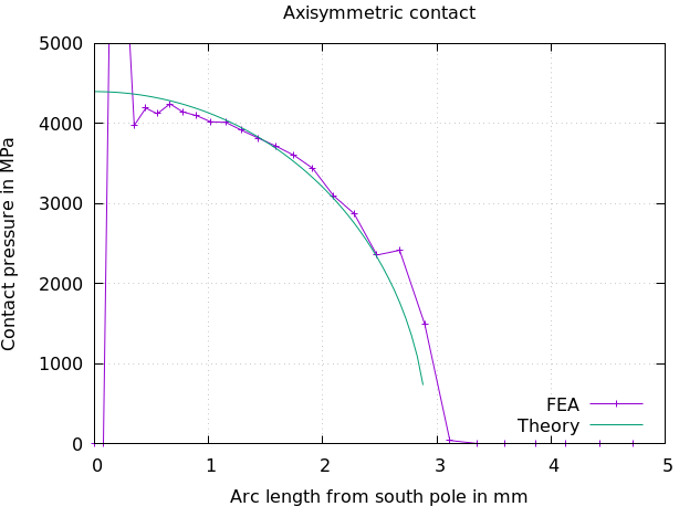
 Stress distribution for a 2D analysis using Ansys
- Kratos
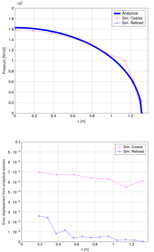 Stress distribution and error in terms of displacement for a 2D analysis using Kratos
- Comsol
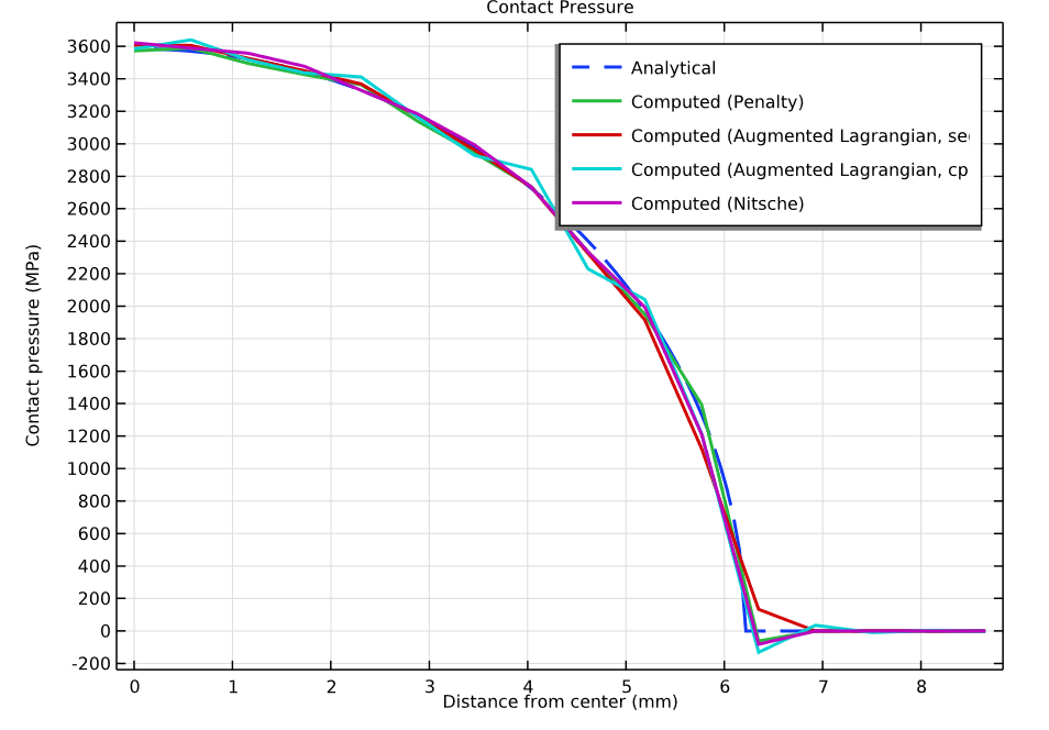 Stress distribution for a 2D analysis using Comsol
 Stress distribution for a 2D analysis using
 -
P. Staubach, J. Machaček, T. Wichtmann: Mortar contact discretisation methods incorporating interface models based on Hypoplasticity and Sanisand: application to vibratory pile driving, Computers and Geotechnics 146:104677, 2022, doi.org/10.1016/j.compgeo.2022.104677 ↩
-
P. Staubach, J. Machaček, T. Wichtmann: Novel approach to apply existing constitutive soil models to the modelling of interfaces, International Journal for Numerical and Analytical Methods in Geomechanics 46(7):1241–1271, 2022, doi.org/10.1002/nag.3344 ↩