Cantilever Beam
In this section, we are examining a cantilever beam of length \(L\) subject to a uniform vertical downward acting load \(q\). The bending curve \(w(x)\) at a given location \(x\) along the beam axis resulting from this load may be computed analytically, rendering it a fitting example for validating the implemented elements. Concurrently, it is also an excellent demonstration of how spatial discretization affects the simulation outcome. For a high-quality simulation result, the element formulation and spatial discretisation are essential factors to consider due to the bending dominant nature of the problem.
In this simulation, the cantilever beam is selected with the following properties:
- External load, \(q=20\) kPa
- Beam length, \(L=1\) m
- Beam width, \(b=1\) m
- Beam height, \(h=0.1\) m
- Youngs' modulus, \(E = 2 \cdot 10^6\) kPa
- \(I = bh^3/12\)
Analytical solution
The deflection along the pile according to beam theory is defined as follows
Input files
The input files for the benchmark simulation can be downloaded here
Results
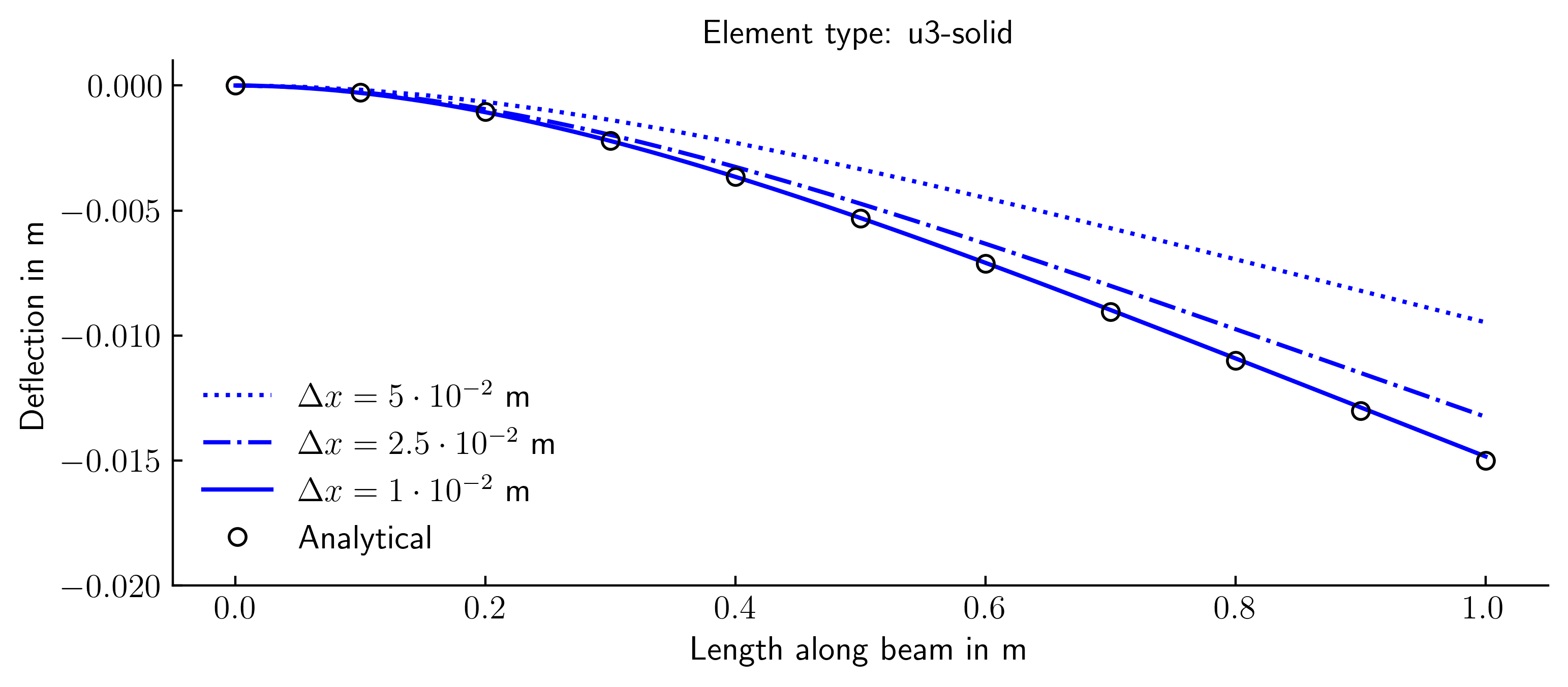
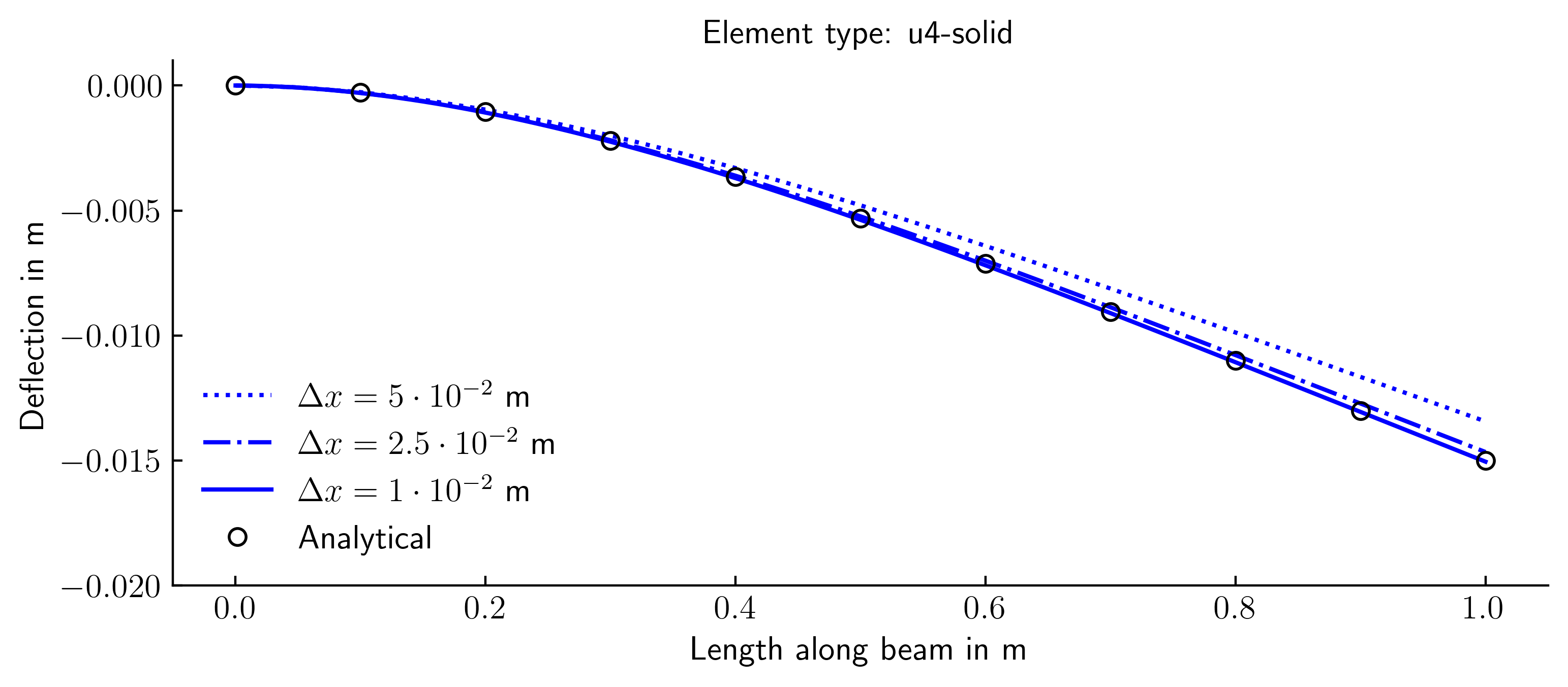
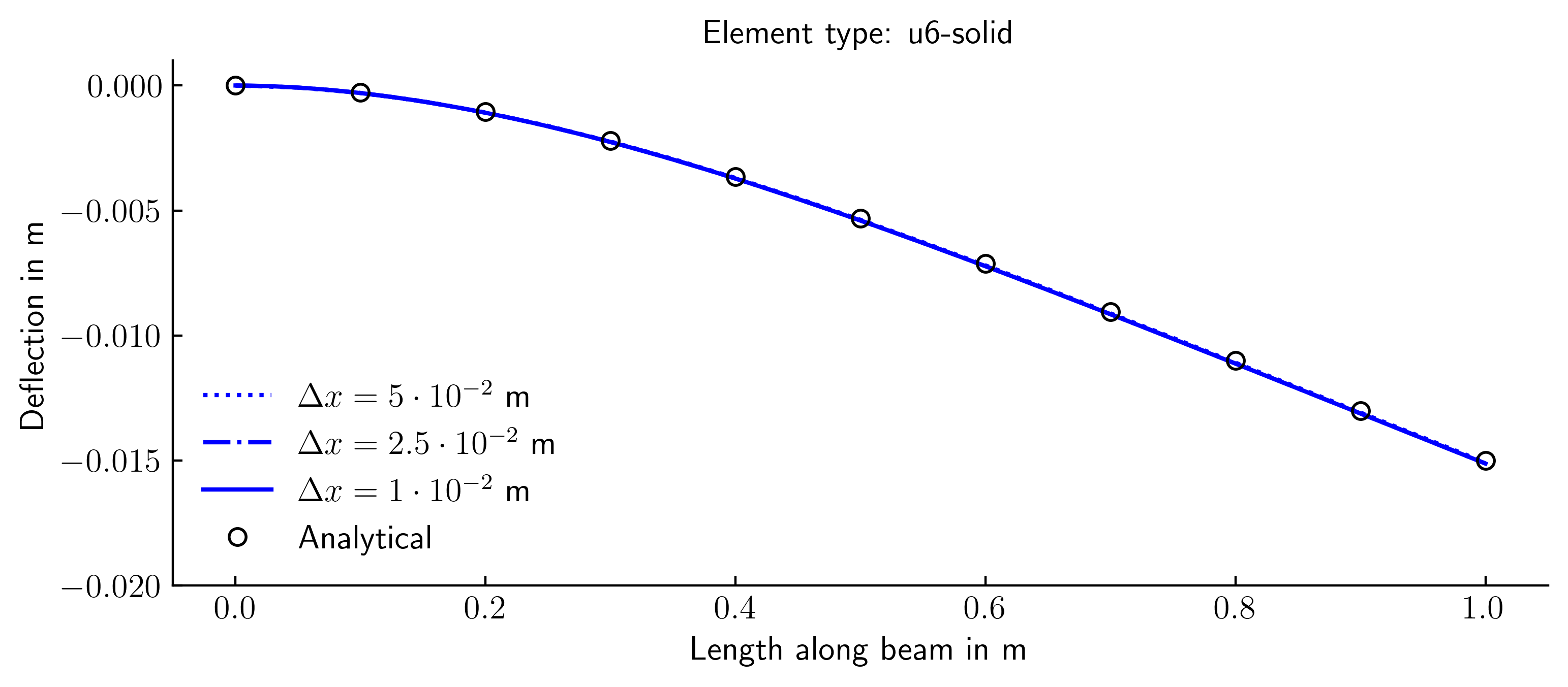
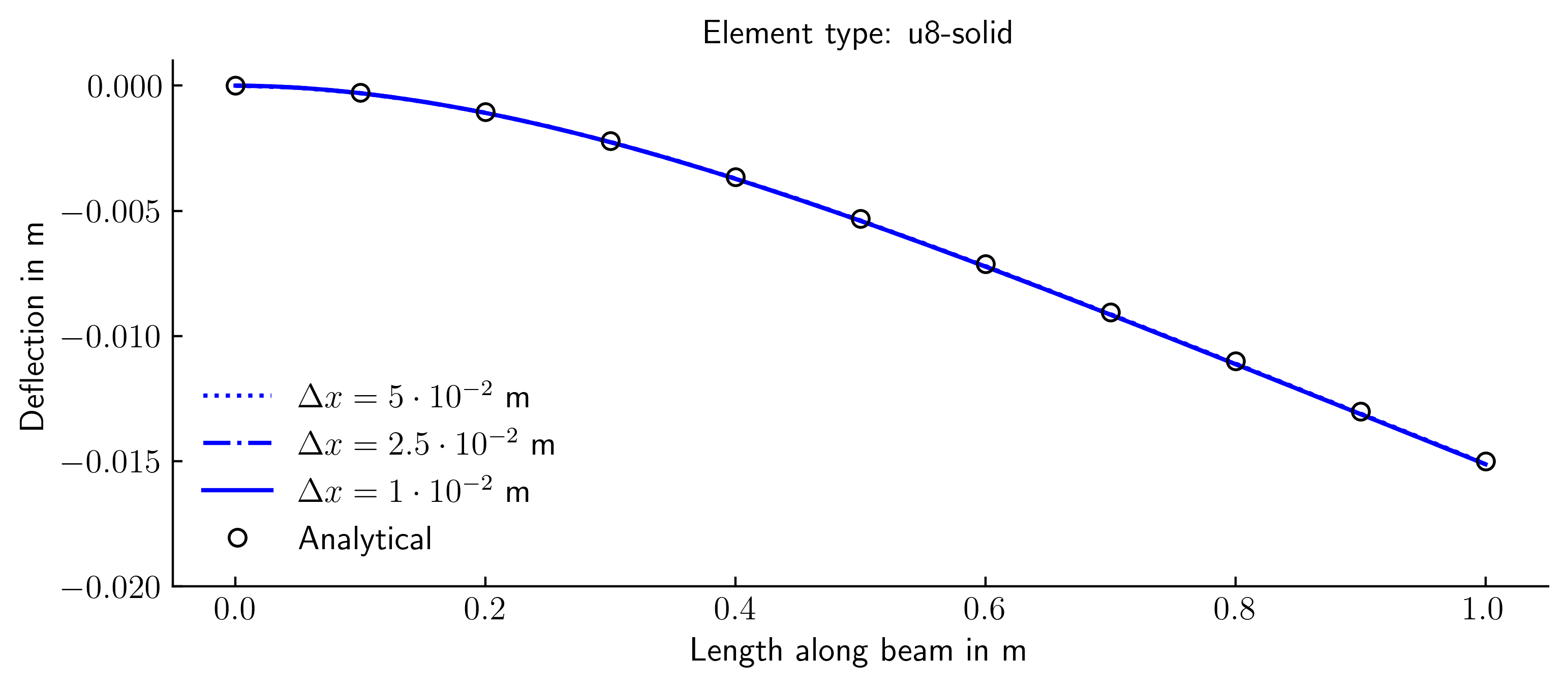
The simulations were conducted using various finite elements and spatial discretisation. The outcomes were compared to the analytically calculated bending line. The bending line in the simulation was derived from the displacement of the top row of nodes of the FE mesh.
U3-solid (2D triangular plane strain elements with 3 nodes)
U4-solid (2D rectangular plane strain elements with 4 nodes)
U6-solid (2D triangular plane strain elements with 6 nodes)
U8-solid (2D rectangular plane strain elements with 8 nodes)
U8-solid-red (2D rectangular plane strain elements with 8 nodes and reduced integration)
