Mesh generation
Introduction
In this example a rigid foundation on a homogeneous soil layer will be studied. The model specifications are shown in Figure 1. The foundation is loaded by a distributed load along the top surface of the foundation and the settlement is studied. The contact will be enforced using the penalty method in conjunction with the mortar approach for the discretisation of the contact area.
First, the mesh generation using the open-source pre-processor platform Salome is discussed. This step can also be skipped and the mesh files directly downloaded.
Following the mesh generation, the following cases are studied:
- Dry elastic soil
- Fully-coupled simulation including the consolidation process
- Fully-coupled simulation with high-cyclic loading using the HCA model
In addition, the model is also used for the demonstration of the user defined extensions discussed here.
 Figure 1. Model of the rigid foundation
The mesh files can be downloaded here.
Mesh generation in Salome
To create the model, open Salome and proceed as explained below.
-
Module
Geometry-
Change to the
Geometrymodule (see Figure 2, (step 1)) in the upper drop-down menu and choose "2D Sketch Construction" (step 2) to create the geometry of the soil area. In the opening window change the "Element Type" to the rectangle (step 3). The coordinates of the left lower and the right upper corner can be left unchanged. Click on "Apply and Close" to finish the sketch Figure 2. Sketch creation in the
 Geometrymodule -
Build a face from the sketch by picking "Build face" (see Figure 3). Leave all options unchanged and mark the line of the previously created rectangle. The face should now be painted magenta and \(Sketch\_1\) should be present in the "Objects" argument. Click on "Apply and Close" to finish the face creation
 Figure 3. Creation of the face of the soil geometry
-
Repeat the same steps to create the foundation
-
Choose 2D Sketch Construction"
-
Change the "Element Type" to the rectangle
-
Change the coordinates to \(X_1 = 0\), \(Y_1 = 10\) and \(X_2 = 1\), \(Y_2 = 10.5\)
-
Finish the sketch
-
Build a face from the sketch
-
-
Create a partition of the face of the soil (see Figure 4)
 Figure 4. Creation of the line used for the partition of the soil
-
Choose "Create a point"
-
In the opening window changes the coordinates to \(X=1\), \(Y=-1\)
-
Create the point using "Apply and Close"
-
Create a second point with the coordinates \(X=1\), \(Y=11\)
-
Choose "Create a line"
-
Pick the lower point and add it to "Point 2" in the opening window
-
Create the line by clicking "Apply and Close"
-
Open the window "Partition" (see step 4 of Figure 4)
-
In the opening window click on the defined line to choose it as "Tool Object" (see Figure 5)
-
Finish the partition by clicking "Apply and Close"
-
Rename the partition to \(soil\)
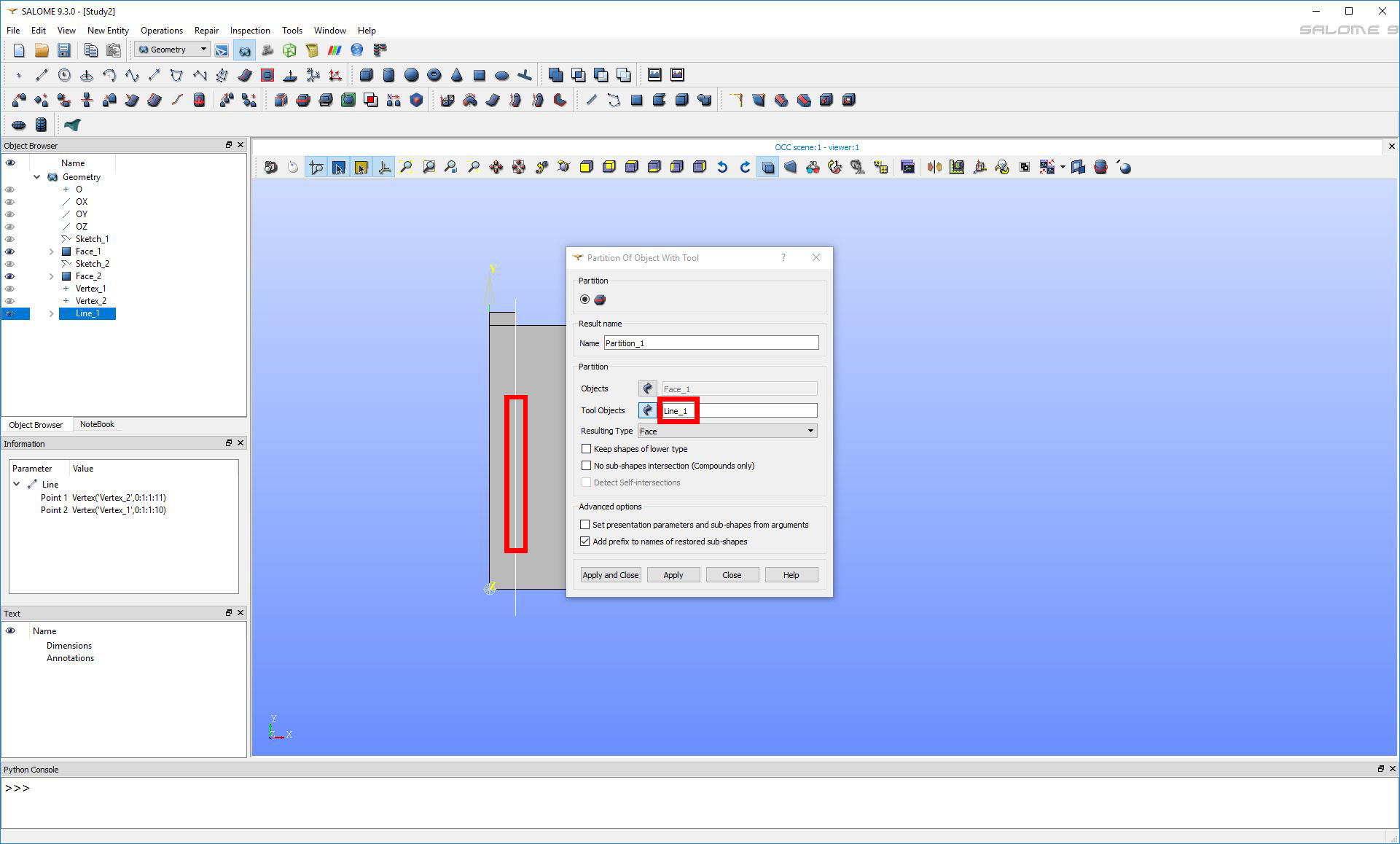 Figure 5. Creation of the partition of the soil
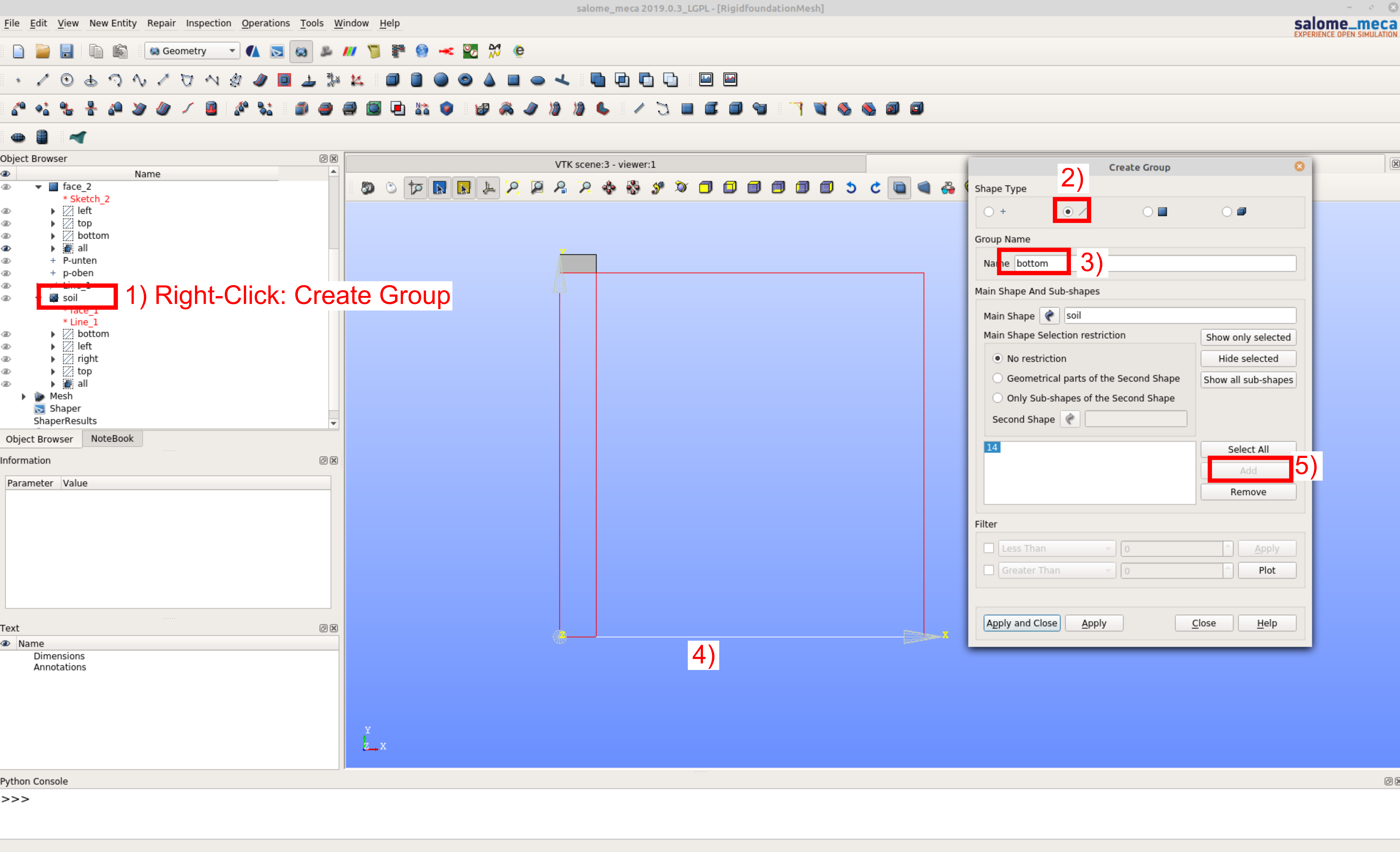 Figure 6. Creation of the line groups (for the face groups change in step 2 to the rectangular blue face)
-
-
Define different groups of geometric entities for the soil by right-clicking on \(Partition\_1\) and choosing "Create Group". In the opening window change the "Shape Type" to edge (inclined line) and define the following groups (see Figure 6):
-
The line group \(bottom\), containing the entire bottom edge of the soil (two individual edges)
-
The line group \(left\), containing the entire left edge of the soil (one individual edge)
-
The line group \(right\), containing the entire right edge of the soil (one individual edge)
-
The line group \(top\), containing the entire top edge of the soil (two individual edges).
-
The face group \(all\) (change the "Face Type" to the 2D face), containing the face of the soil (two individual faces)
-
-
Define different groups of geometric entities for the foundation by right-clicking on \(Face\_2\) and choosing "Create Group". In the opening window change the "Shape Type" to edge (inclined line) and define the following groups:
-
The line group \(left\), containing the entire left edge of the foundation (one individual edge)
-
The line group \(bottom\), containing the lower edge of the foundation (one individual edge).
-
The line group \(top\), containing the top edge of the foundation (one individual edge)
-
The face group \(all\) (change the "Face Type" to the 2D face), containing the face of the foundation (one individual face)
-
-
-
Module
Mesh-
Change to the
Meshmodule (see Figure 7, (step 1)) in the upper drop-down menu and change the view orientation (step 2). Click on "Create Mesh" (step 3) and mark \(Soil\). Choose "Quadrangle: Mapping" as "Algorithm". Change to 1D and choose:-
"Algorithm": "Wire Discretisation"
-
In "Hypothesis" click on the gearwheel, select "Local Length" and define 0.2 as "Length"
-
"Apply and Close"
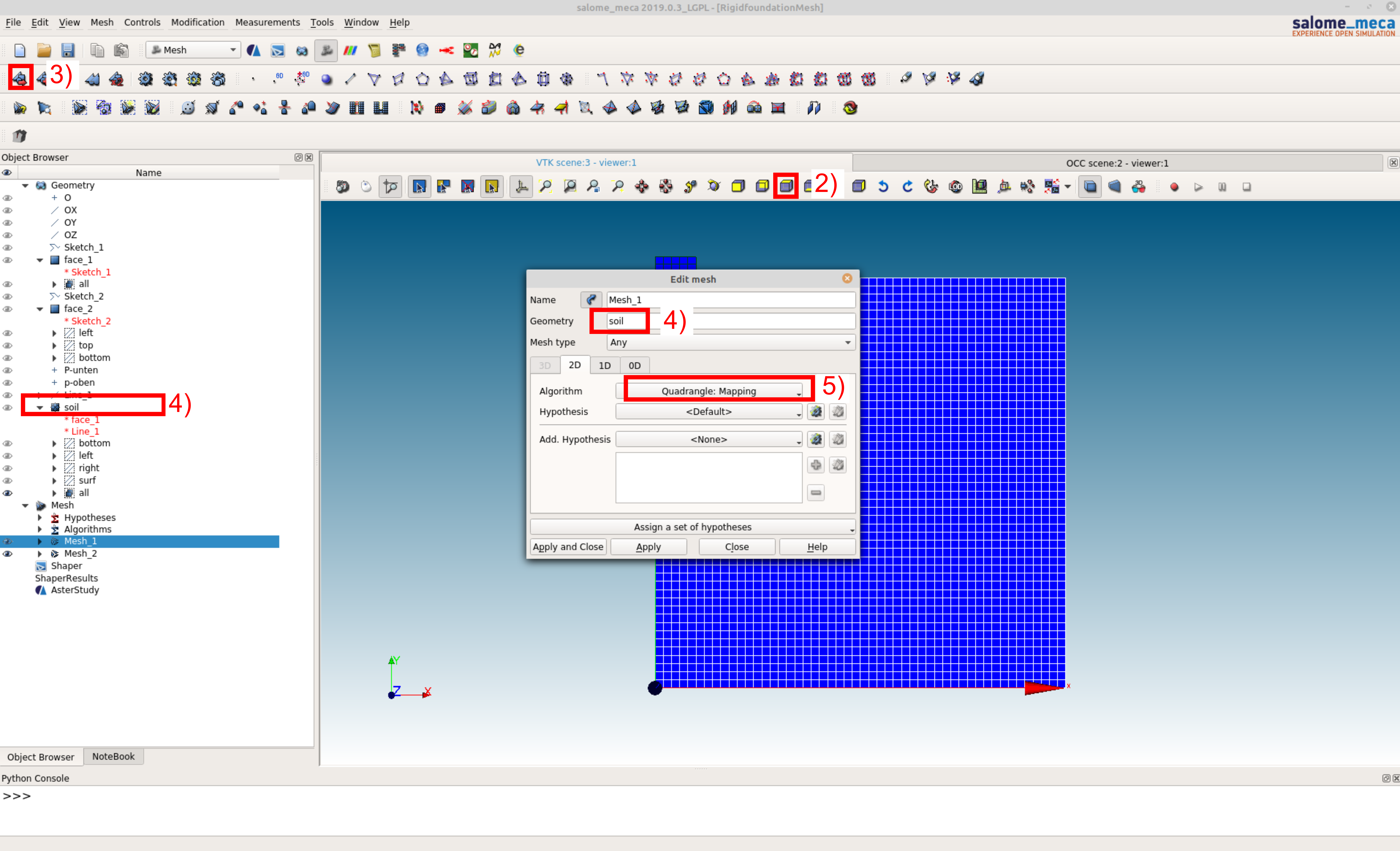 Figure 7. Generation of the mesh
-
-
Right-click on \(Mesh\_1\), "Compute"
-
Repeat the same steps for the foundation and create \(Mesh\_2\)
-
Import the previous defined groups by right-clicking on \(Mesh\_1\) and choose "Create Groups from Geometry" (see Figure 8). Mark the groups shown in Figure 8(using ctrl) in the "Object Browser" from \(Soil\) and add them to the elements as well as to the nodes
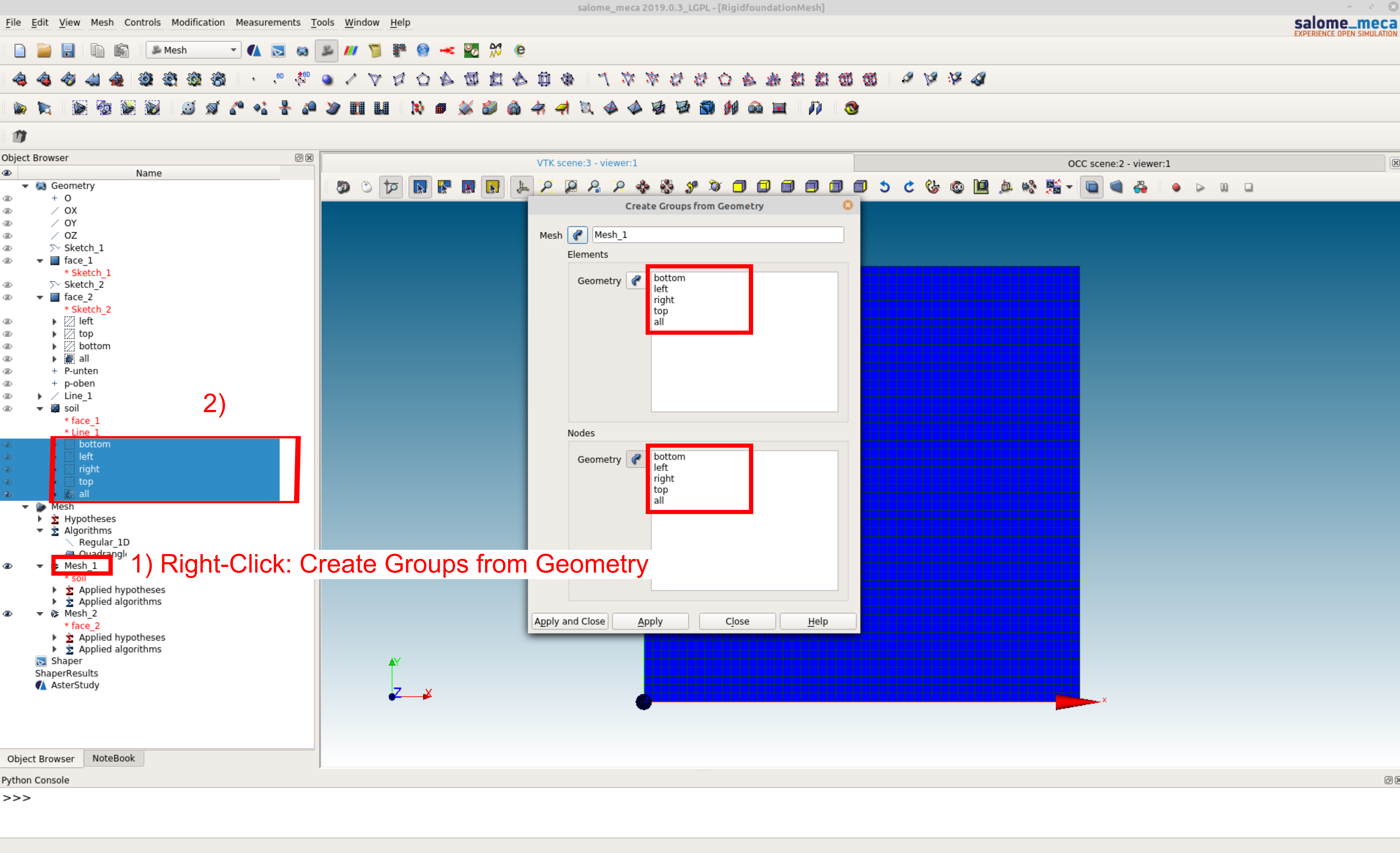 Figure 8. Importing the groups into the mesh
-
Right-click on \(Mesh\_1\) \(\rightarrow\) "Convert to/from quadratic", pick "Convert to quadratic"
-
Export the model by selecting \(Mesh\_1\) in the "Object Browser" and go to File \(\rightarrow\) Export \(\rightarrow\) UNV file and save the file to the desired destination with the name \(mesh-soil\)
-
Repeat the same steps for the foundation and save as \(mesh-foundation\)
-
-
To translate the .UNV file to an input file in the format of
numgeo, the numgeo-API python script is used-
Copy the file "example.py" to the same directory as the .UNV file and
-
Change the filenames in "example.py" to the name of the .UNV file according to Figure 9. In addition, set the names of the parts, their dimension and the element type according to the example script.
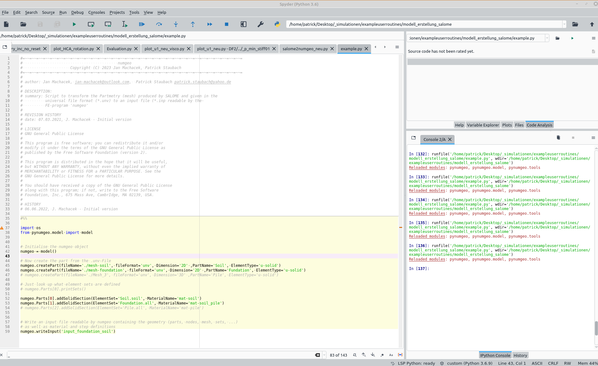 Figure 9. Settings in the python script
-
Run the script either using the IDE Sypder or over a python console
-
An input file with the name specified in line 59 of the python script is created
-
-
In some cases, SALOME meshes with a clockwise arrangement of nodes for the individual elements. This will result in a negative element area and therefore an error.
numgeowill in this case write a message in the console notifying the user that the Jacobian determinate of the element is negative. This error can be resolved using the option "Orientation" in theMeshmodule of SALOME. Choose this option, add the entire mesh (Apply to all) and apply the change of orientation