Beam elements
Upcoming release
Beam elements will be available with the upcoming release
Beam elements are structural members capable of resisting axial forces, shear forces, and bending moments. They model slender structural elements where one dimension is significantly larger than the other two. Beam elements include both Euler-Bernoulli and Timoshenko beam theories, with the latter accounting for shear deformation effects. Details on the implementation are provided in the Theory Manual.
The properties of beam elements are assigned using the *Material keyword in combination with the *Beam properties sub-keyword. See the Reference Manual for more information.
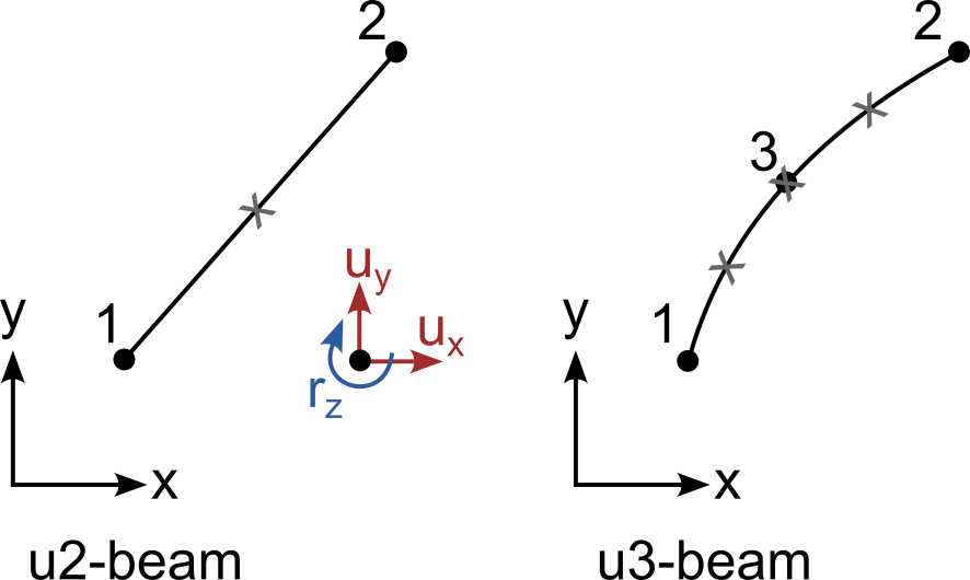
2D Elements
| Element label | Dim. | Shape | Nodes | Order | nIP* |
|---|---|---|---|---|---|
u2-beam |
2D | beam | 2 | linear | 1 |
u3-beam |
2D | beam | 3 | quadratic | 3 |
* nIP = number of integration points
3D Elements
| Element label | Dim. | Shape | Nodes | Order | nIP* |
|---|---|---|---|---|---|
u2-beam-3D |
3D | beam | 2 | linear | 1 |
u3-beam-3D |
3D | beam | 3 | quadratic | 3 |
* nIP = number of integration points
Notes on output
For Beam elements, \(\sigma_{11}\) is the axial stress and \(\sigma_{12}\) and \(\sigma_{13}\) correspond to the shear stresses in local xy and xz-direction, respectively. All other components are zero.
Similarly, \(\varepsilon_{11}\) is the axial strain and \(\varepsilon_{12}\) and \(\varepsilon_{13}\) correspond to the shear strains in local xy and xz-direction, respectively.
In addition to general output in cartesian coordinates such as displacements, stress and strain, local quantities can be requested:
Beam-Force-N: normal force along the beam axis in FBeam-Force-Qy: shear force in local y-axis in FBeam-Force-Qz: shear force in local z-axis in FBeam-Moment-Mz: bending moment around local z-axis in F·LBeam-Moment-My: bending moment around local y-axis in F·L
See the Theory Manual for information about the calculation of forces and bending moments.