User defined material
The input files can be downloaded here.
In this example the use of user defined material (mechanical) model is demonstrated. For this purpose we consider the same rigid foundation on an elastic soil layer already studied in the tutorial Rigid strip footing. The model specifications are shown in Figure 1. The foundation is loaded by a distributed load along the top surface of the foundation and the settlement is studied assuming ideally drained conditions and a linearly increasing external load (\(\Delta \sigma_v(t=0 ~\text{s}) = 0\) kPa and \(\Delta \sigma_v(t=1 ~\text{s})=500\) kPa).
 Figure 1. Model of the rigid foundation
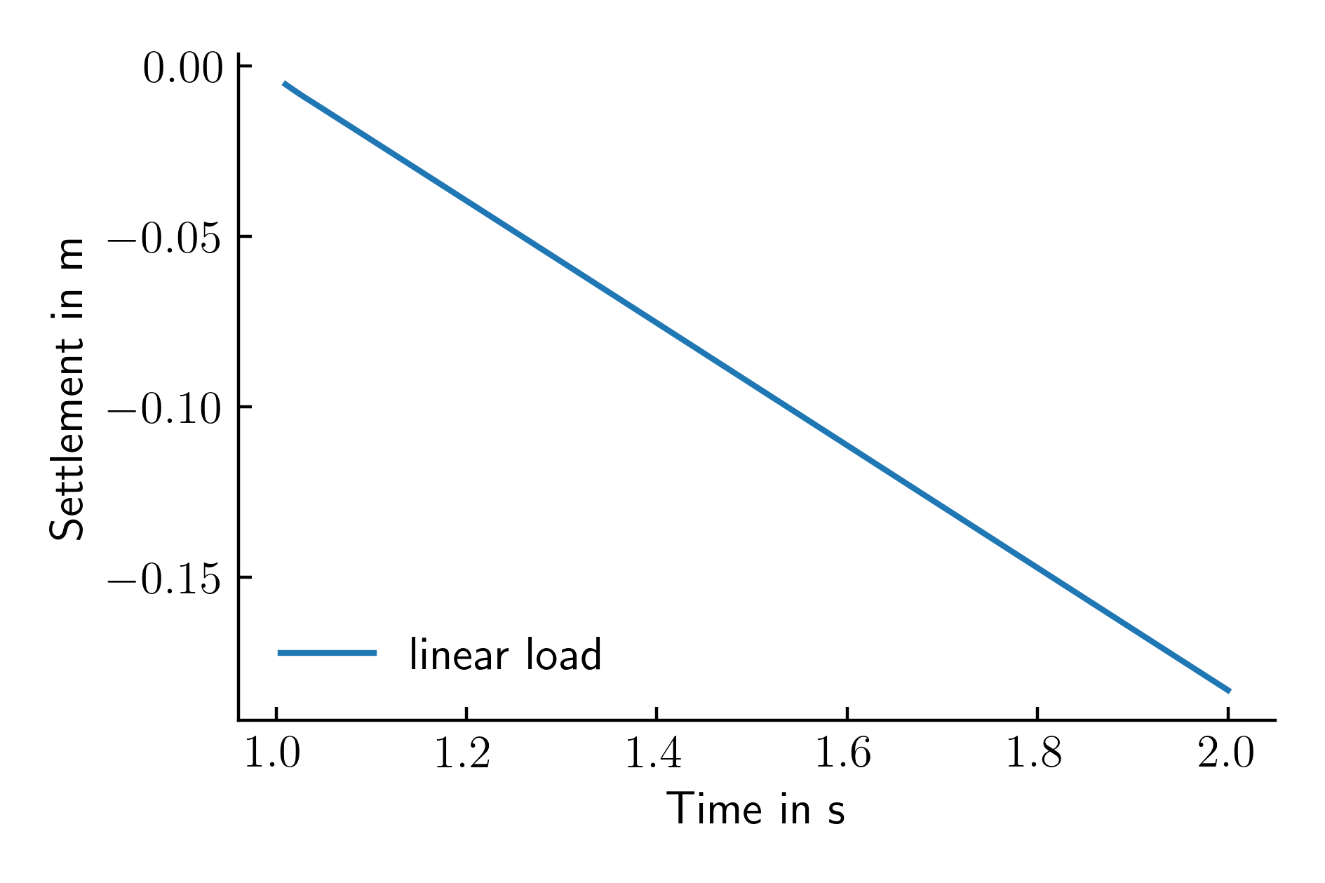
The resulting vertical displacements of the top left node of the shallow foundation are reported in Figure 2.

Figure 2. Settlement time history of the top left node of the shallow foundation
For the sake of this tutorial we will now consider a slightly more complicated stress-strain relation. Instead of a linear elasticity with a constant Young's modulus, we now want to consider a pressure-dependent stiffness of the following form
Compared to the linear elastic constitutive model, this constitutive model requires 3 more material parameters: the reference stiffness \(E_0\) at \(p=p_{ref}\), the exponent \(n\) and the reference pressure \(p_{ref}\). Due to its simplicity this model does not require the definition of any state variables. However, for output purposes we would like to be able to track the development of \(f_p\) and \(E\), thus defining two state variables for the user material. In order to replace the linear elastic model for the soil by the user defined material model we use the following code snipped in the input file of numgeo:
*Material, name = soil, phases = 1
*Mechanical = user
*User properties, props=4, statev=2
5000, 0.3, 0.2, 1
*Density
2.0
The material definition is very similar to using a material model already implemented in numgeo. The *Mechanical=user command tells numgeo to use a material model that is not available in the internal library. The material parameters are then set using the *User properties command. In this line the number of material parameters (props=) and state variables (statev=) must also be specified.
In the present case we have a total of 4 properties (\(E_0=5000\) kPa, \(\nu=0.3\), \(n=0.2\) and \(p_{ref}=1\) kPa) and the number of state variables is 2 (\(f_p\) and \(E\)).
Since we want to see the evolution of the state variables \(f_p\) and \(E\) in the field output (Paraview) we need to modify the output request as follows:
*Output, field, vtk, ASCII
...
*Element output, elset = Soil.all
S, Contact, sdv1, sdv2
Output variables starting with sdv followed by a number are state variables of constitutive models that have not (yet) been saved by name. For example, for hypoplasticity with intergranular strain, the void ratio can be initialised with void_ratio or the intergranular strain can be initialised with int_strain11, int_strain12, ..., int_strain33 or requested directly as output.
For the "freely assignable" state variables, sdv1 = statev(1), sdv2 = statev(2), ... Here statev(:) is the array containing the state variables of the model. If a user-defined constitutive model is implemented, the correct implementation of the evolution equation of the state variables is the responsibility of the user.
Next, we copy the files user_material.f90 and user_material.bat to the directory where we want to run the simulation. Once the files are relocated, we implement above equation into the Fortran file:
subroutine user_material(material_name,nchar,ielem,igp,istep,iinc,ntens,nprops,nstatev, &
    strain,dstrain,coords,time,dtime,props,statev,stress,dds_dde)
    implicit none
    !DEC$ ATTRIBUTES DLLEXPORT, STDCALL, REFERENCE :: user_material
    character                       , intent(in) :: material_name(*)
    integer                         , intent(in) :: nchar
    integer                         , intent(in) :: ielem
    integer                         , intent(in) :: igp
    integer                         , intent(in) :: istep
    integer                         , intent(in) :: iinc
    integer                         , intent(in) :: ntens
    integer                         , intent(in) :: nprops
    integer                         , intent(in) :: nstatev
    real(8), dimension(ntens)       , intent(in) :: strain
    real(8), dimension(ntens)       , intent(in) :: dstrain
    real(8), dimension (3)          , intent(in) :: coords
    real(8)                         , intent(in) :: time
    real(8)                         , intent(in) :: dtime
    real(8), dimension(nprops)      , intent(in) :: props
    real(8), dimension(nstatev)     , intent(inout) :: statev
    real(8), dimension(ntens)       , intent(inout) :: stress
    real(8), dimension(ntens ,ntens), intent(inout) :: dds_dde

    character(len=nchar) :: material_str

    real(c_double) :: E, nu, k1, k2, k3
    real(8) :: E0, nu, n, pref
    real(8) :: E, fp, p
    real(8) :: k1, k2, k3

    ! required to make the material name usable in select case of if-clauses
    material_str = transfer(material_name(1:nchar), material_str)

    dds_dde = 0.0d0
    E0 = props(1) ; nu = props(2) ; n = props(3) ; pref = props(4)

    p = -sum(stress(1:3))/3.0d0

    fp = (max(pref,p)/pref)**n
    E = E0 * fp

    k1 = nu * E / (1.0d0+nu) / (1.0d0-2.0d0*nu)
    k2 = E / 2.0d0 / (1.0d0+nu)
    k3 = k1 + 2.0d0 * k2

    dds_dde(1:3,1:3) = k1
    dds_dde(1,1) = k3 ; dds_dde(2,2) = k3 ; dds_dde(3,3) = k3
    dds_dde(4,4) = k2

    if (ntens == 6) then
    dds_dde(5,5) = k2
    dds_dde(6,6) = k2
    end if

    stress = stress + matmul(dds_dde,dstrain)

    statev(1) = fp
    statev(2) = E

end subroutine user_material
subroutine user_material(material_name,nchar,ielem,igp,istep,iinc,ntens,nprops, &
    nstatev,strain,dstrain,coords,time,dtime,props,statev,stress,dds_dde) &
    bind(c,name='user_material')
    use, intrinsic :: iso_c_binding
    implicit none
    character(c_char)                      , intent(in) :: material_name (*)
    integer(c_int)                         , intent(in) :: nchar
    integer(c_int)                         , intent(in) :: ielem
    integer(c_int)                         , intent(in) :: igp
    integer(c_int)                         , intent(in) :: istep
    integer(c_int)                         , intent(in) :: iinc
    integer(c_int)                         , intent(in) :: ntens
    integer(c_int)                         , intent(in) :: nprops
    integer(c_int)                         , intent(in) :: nstatev
    real(c_double), dimension(ntens)       , intent(in) :: strain
    real(c_double), dimension(ntens)       , intent(in) :: dstrain
    real(c_double), dimension (3)          , intent(in) :: coords
    real(c_double)                         , intent(in) :: time
    real(c_double)                         , intent(in) :: dtime
    real(c_double), dimension(nprops)      , intent(in) :: props
    real(c_double), dimension(nstatev)     , intent(inout) :: statev
    real(c_double), dimension(ntens)       , intent(inout) :: stress
    real(c_double), dimension(ntens ,ntens), intent(inout) :: dds_dde

    character(len=nchar) :: material_str

    real(c_double) :: E, nu, k1, k2, k3
    real(c_double) :: E0, nu, n, pref
    real(c_double) :: E, fp, p
    real(c_double) :: k1, k2, k3

    ! required to make the material name usable in select case of if-clauses
    material_str = transfer(material_name(1:nchar), material_str)

    dds_dde = 0.0d0
    E0 = props(1) ; nu = props(2) ; n = props(3) ; pref = props(4)

    p = -sum(stress(1:3))/3.0d0

    fp = (max(pref,p)/pref)**n
    E = E0 * fp

    k1 = nu * E / (1.0d0+nu) / (1.0d0-2.0d0*nu)
    k2 = E / 2.0d0 / (1.0d0+nu)
    k3 = k1 + 2.0d0 * k2

    dds_dde(1:3,1:3) = k1
    dds_dde(1,1) = k3 ; dds_dde(2,2) = k3 ; dds_dde(3,3) = k3
    dds_dde(4,4) = k2

    if (ntens == 6) then
    dds_dde(5,5) = k2
    dds_dde(6,6) = k2
    end if

    stress = stress + matmul(dds_dde,dstrain)

    statev(1) = fp
    statev(2) = E

end subroutine user_material
The shell script guiding the compilation of the user defined amplitude is as follows:
ifort -O3 /dll user_material.f90
#!/bin/bash
ifort -c -shared -fPIC user_material.f90
ifort -shared -fPIC user_material.o -o user_material.so
The simulation can now be started from the terminal using the standard procedure, e.g.
numgeo inp=input out=simulation ncpus=4
./numgeo inp=input out=simulation ncpus=4
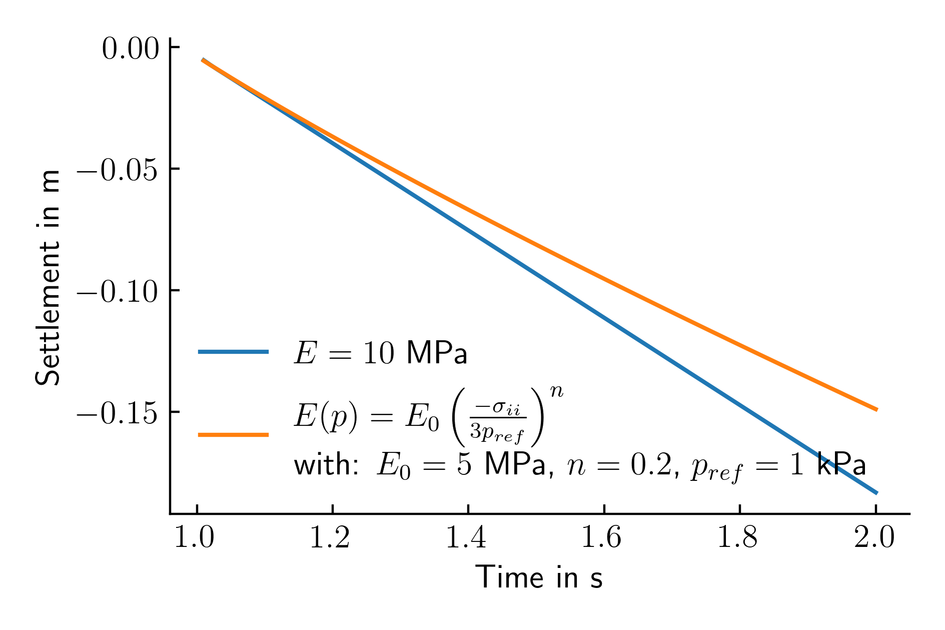
numgeo will automatically compile the user subroutine user_material.f90 and link it to the code. The resulting settlement-time history is given in Figure 3 and compared to the reference simulation using a linear elastic model.

Figure 3. Settlement time history of the top left node of the shallow foundation for a linear increasing load for two different constitutive models for the soil
As expected we observe a reduced settlement (orange) at the end of the simulation compared to the reference solution (blue) due to the increase in stiffness with increasing mean effective stress.
Plotting the results
For plotting the results as shown in above figures, the following python script can be used:
#%%
import numpy as np
import matplotlib.pyplot as plt

plt.rcParams['xtick.direction'] = 'in'
plt.rcParams['ytick.direction'] = 'in'
plt.rcParams['text.usetex'] = True
plt.rcParams['font.size'] = 12
plt.rcParams['axes.spines.right'] = False
plt.rcParams['axes.spines.top'] = False

def cm2inch(*tupl):
    inch = 2.54
    if isinstance(tupl[0], tuple):
        return tuple(i/inch for i in tupl[0])
    else:
        return tuple(i/inch for i in tupl)

node_set_name = "FOUNDATION.TOP_LEFT_NODE_node_7703.dat"

ref = np.genfromtxt("./reference/simulation-print-out/"+node_set_name, skip_header=1)
data = np.genfromtxt("./user material/simulation-print-out/"+node_set_name, skip_header=1)

plt.figure(figsize=cm2inch(12,8))
plt.plot(ref[:,0], ref[:,2], label='$E=10$ MPa')
plt.plot(data[:,0], data[:,2], label='$E(p) = E_0 \\left( \\frac{-\sigma_{ii}}{3p_{ref}} \\right)^n$ \n with: $E_0=5$ MPa, $n=0.2$, $p_{ref}=1$ kPa')
plt.xlabel('Time in s')
plt.ylabel('Settlement in m')
plt.legend(loc='lower left', frameon=False)
plt.tight_layout()
plt.savefig('./time_settlement_user_material.pdf', dpi=400)
plt.savefig('./time_settlement_user_material.png', dpi=400)