Spring-ground-t: elastic block on a linear tangential spring bed
This benchmark verifies Spring-ground-t and its relative formulation against a closed-form solution. A rectangular, linear-elastic body occupying \([0,1.0]\times[0,0.1]\) m (plane strain, unit out-of-plane thickness) is vertically confined (\(u_y=0\)) on its base edge, an additional set a set of (tangential) Spring-ground-t springs acting in horizontal direction is applied to the base edge, and loaded by a uniform pressure \(p\) on the right edge. Self-weight is neglected, so that the only load is the applied pressure.
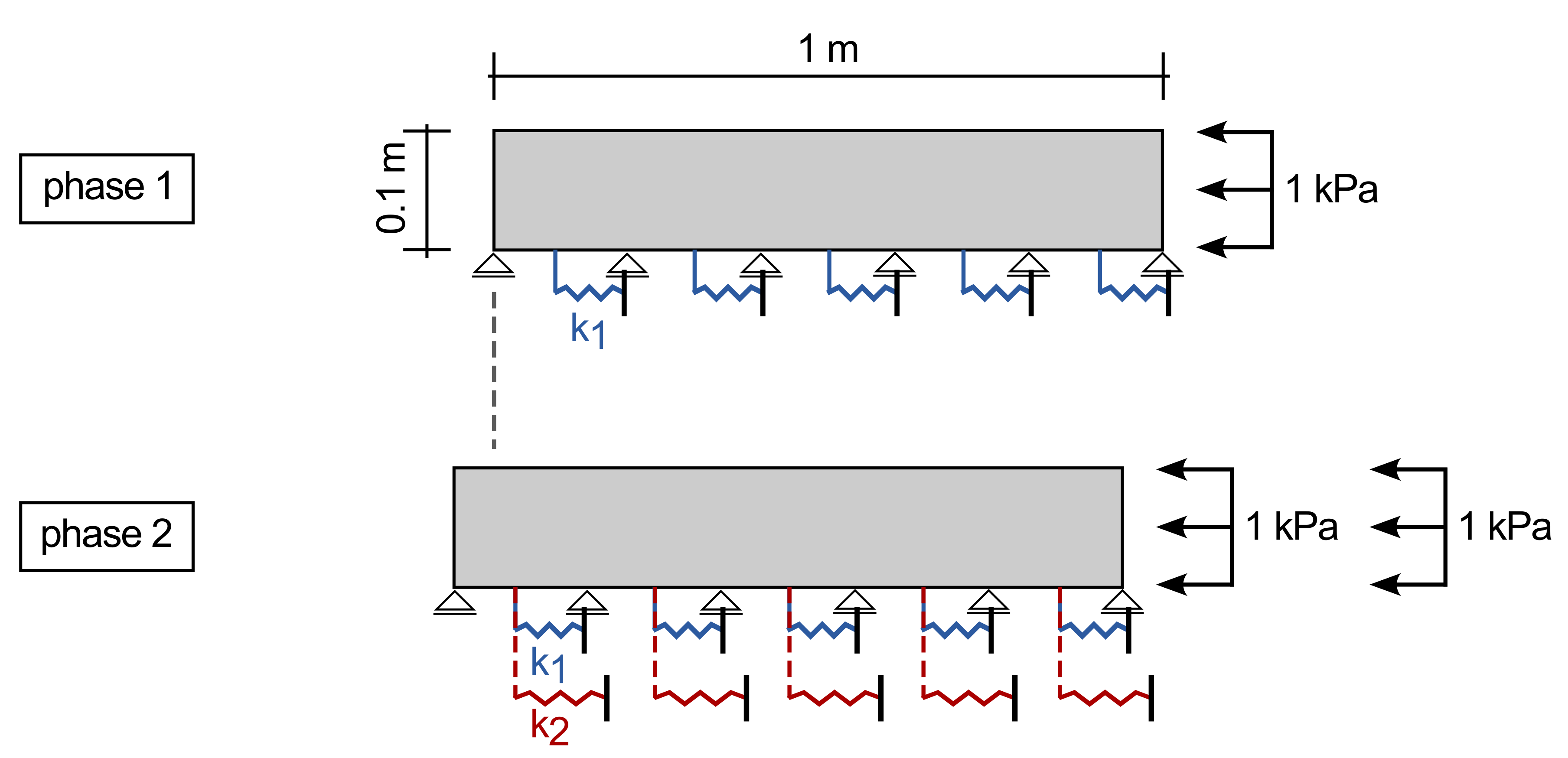
Figure 1: Model setup (not to scale).
The linear-elastic body is modelled using a Young's modulus of 2 GPa and a Poisson's ratio of 0.3. The simulation consists of two phases:
- Phase 1: along the base edge a set of tangential springsa acts in global horizontal direction with constant stiffness of \(k_1=10\) kN/m. A compressive load is applied at the right edge of the body. The load is linearly increasing from 0 kPa to 10 kPa over a time of 1 second (quasi-static conditions).
- Phase 2: An additional set of springs is attached to the base of the model, again acting in tangential direction. The spring stiffness is \(k_2=20\) kN/m. The springs are added strain-free, relative to the current configuration. The load from phase 1 remains constant in this phase but is augmented by a second compressive load, again linearly increasing from 0 kPa to 1 kPa over a time of 1 seconds such that at the end of the phase, a total of 2 kPa is acting on the right edge of the body.
Input files
Download the input file here
Results
Neglecting self-weight, horizontal equilibrium of the body requires the horizontal stress \(\sigma_{xx}\) to be constant within the body, so the spring reaction exactly equals the applied pressure, \(q_{\text{spring}}=1\), and the horizontal movement due to spring compression alone is
with the area/length \(A^r=0.1\) m of the right edge. The body's own uniaxial-strain compression can be neglected due to the combination of low external pressure (max 2 kPa) and high Young's modulus.
The total hzorizontal displacement of the loaded (right) edge is therefore
For stage one, the resulting displacements are
The horizontal displacement at the end of phase 2 are a result of the displacements of phase 1 and any additional displacements from the newly applied load. The springs \(k_1\) and \(k_2\) act in parallel, such that the final displacements at the end of phase 2 are calculated as
A comparison of the simulation results and the analytical ones is given in Figure 2.
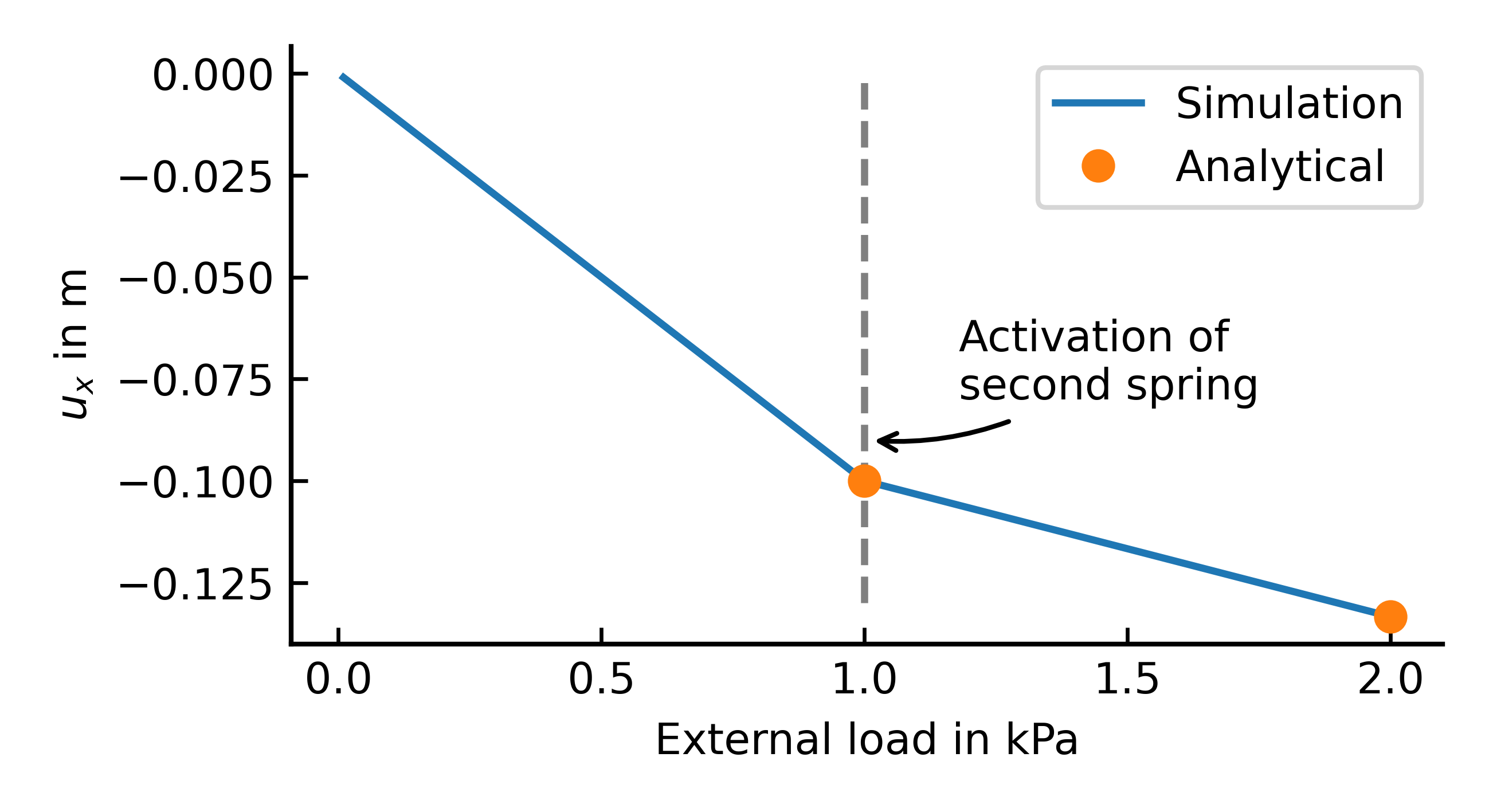
Figure 2: Simulation results vs. analytical results for the spring supported elastic body under uniform compressive load