Interaction (embedded beams)
The method *Embedded region, interaction couples line (guest) elements - trusses or beams - to a region of continuum (host) elements using distributed interface springs, following the embedded beam concept frequently used for grouted anchors, soil nails and micro piles. In contrast to the absorbed method, the guest elements retain their independent degrees of freedom; the interaction with the host region is described by an interface law acting on the relative displacement between the guest elements and the surrounding host material, numerically integrated over the embedded length.
Upcoming release
The *Embedded region, interaction feature will be available with the upcoming release
Internal nodes and internal element
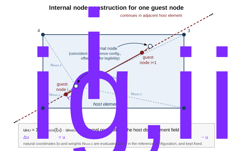
Figure 1: for each guest node, an internal node is generated at the same (reference) location and slaved to the host element's displacement field. The dashed lines and \(N_{host,k}\) weights are evaluated once and kept fixed.
For each node \(i\) of an embedded guest element, an internal node is generated at the same location \(\boldsymbol{X}_i\). Upon construction of the embedded region (see Determine host elements), the host element containing the guest node and the natural coordinates \(\boldsymbol{\xi}^h_i\) of the guest node within this host element are determined. The internal node is slaved to the displacement field of its host element:
where \(N_{host,k}\) are the shape functions of the host element and \(\boldsymbol{u}^h_k\) the displacements of its nodes. The natural coordinates \(\boldsymbol{\xi}^h_i\) are evaluated once in the reference configuration and kept fixed (Lagrangian coupling).
The internal nodes form an internal 1D element with the same connectivity and shape functions \(N_i(\xi)\) as the guest element. The relative displacement field between the guest element and the internal element reads
It is convenient to collect all participants \(p\) of one guest element - its own nodes and the nodes of the host elements of each of its nodes - and to write the relative displacement at a point \(\xi\) as a weighted sum
with the participation factors \(\bar{w}_{p,i} = 1\) if \(p\) is the guest node \(i\) itself, \(\bar{w}_{p,i} = -N_{host,k}(\boldsymbol{\xi}^h_i)\) if \(p\) is the node \(k\) of the host element of guest node \(i\), and \(\bar{w}_{p,i} = 0\) otherwise.
Interface law
The interface law acts on the relative displacement \(\Delta\boldsymbol{u}\), decomposed into an axial part along the (reference) beam axis \(\boldsymbol{a}\) and a lateral part:
The axial direction \(\boldsymbol{a}\) is the normalised tangent of the guest element in the reference configuration, evaluated at the integration point.
Axial direction: an elastic - perfectly plastic slider with stiffness \(k_t\) (per unit length) and, optionally, an ultimate skin traction \(t_{ult}\) (per unit length). With the plastic slip \(\gamma\) (state variable, stored per integration point) the trial traction and the return mapping read
where \(\gamma_n\) denotes the converged plastic slip of the previous increment. The plastic slip is committed upon global convergence of the increment. If \(t_{ult}\) is not provided, the axial behaviour is linear elastic (\(t_s = k_t\, \Delta u_s\)).
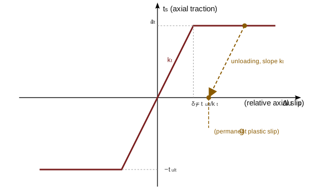
Figure 2: axial bond-slip law. The traction saturates at \(\pm t_{ult}\); it does not drop, and the interface does not disengage. Unloading/reloading follows the elastic slope \(k_t\) and leaves a permanent slip \(\gamma\).
Stress-dependent axial capacity (Mohr-Coulomb): with type=Mohr-Coulomb, the constant \(t_{ult}\) is replaced by a Mohr-Coulomb capacity computed from the stress state of the surrounding host material:
with the interface cohesion (adhesion) \(c\), the interface friction angle \(\varphi\), the shear surface per unit anchor length \(A_s\) and the mean lateral stress \(\sigma_n\) - the mean of the normal stresses acting perpendicular to the anchor axis, a rotation-invariant scalar surrogate for the radial stress varying around the circumference (identical expression in 2D, where it includes the out-of-plane stress \(\sigma_{33}\), and in 3D). With numgeo's tension-positive stresses, compressive \(\sigma_n < 0\) increases the capacity; the \(\max(\cdot, 0)\) is the tension cutoff. The return mapping and the algorithmic stiffness are those of the constant-capacity slider, with \(t_{ult}\) replaced by \(t_{cap}(\xi_{gp})\) evaluated per integration point.
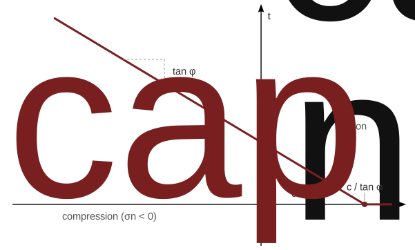
Figure 3: Mohr-Coulomb axial capacity. The cohesion \(c\) carries the interface at zero normal stress; compression increases the capacity with slope \(\tan\varphi\); tensile \(\sigma_n \ge c/\tan\varphi\) reduces it to zero (cutoff).
The host stress is mapped onto the anchor through the same internal-node pipeline used for the displacements: for each guest node, the mean of the converged effective stresses over the integration points of its host element is taken; these nodal tensors are interpolated along the guest element with \(N_i(\xi)\) to the integration points, where the projection \(\sigma_n\) and the capacity \(t_{cap}\) are evaluated. Since the host element stresses are effective stresses, coupled (u-p) analyses automatically yield an effective-stress friction criterion. Using the converged stresses (rather than the current iterate) means the capacity is constant within each increment: the consistent linearisation of the slider (\(k_t^{alg} = 0\) during sliding) remains exact and no unsymmetric coupling term \(\partial t_{cap} / \partial \boldsymbol{u}^h\) arises; the price is that the capacity lags the host stress state by one increment, which is irrelevant for monotonic loading and benign otherwise.
Lateral direction: a linear elastic spring with stiffness \(k_n\) (per unit length):
The total interface traction (force per unit length) is \(\boldsymbol{t} = t_s\, \boldsymbol{a} + \boldsymbol{t}_\perp\) and the consistent interface modulus reads
with the algorithmic axial stiffness \(k_t^{alg} = k_t\) in the elastic regime and \(k_t^{alg} = 0\) during plastic sliding. Note that \(\boldsymbol{D}\) is diagonal in the \((\boldsymbol{a}, \perp)\) basis: the axial and lateral responses are uncoupled.
Numerical integration and assembly
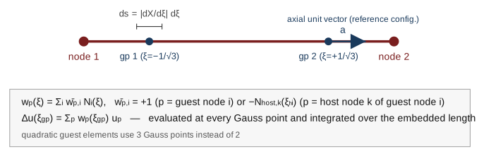
Figure 4: the relative displacement and the interface law are evaluated at the Gauss points of the guest element and integrated over the embedded length \(\mathcal{L}\); \(\mathrm{d}s\) and \(\boldsymbol{a}\) are computed once, from the reference geometry.
The virtual work of the interface tractions along the embedded length \(\mathcal{L}\) of a guest element,
is evaluated by Gauss integration at the integration points of the guest element (2 points for linear, 3 points for quadratic interpolation), with the length increment \(\mathrm{d}s = \| \mathrm{d}\boldsymbol{X}/\mathrm{d}\xi \| \, \mathrm{d}\xi\) computed from the reference geometry of the guest element. The consistent nodal force contribution of a participant \(p\) and the coupled stiffness contribution between participants \(p\) and \(q\) read
The interface forces are treated as (solution dependent) external loads, i.e. they enter the right-hand side via \(\boldsymbol{f}^{ext}\) and their linearisation enters the left-hand side following the same sign convention as the ground springs. Note that the forces act once on the guest nodes (\(\bar{w} = +1\)) and once - with opposite sign, distributed via the host shape functions (\(\bar{w} = -N_{host}\)) - on the nodes of the host elements: the formulation is action = reaction by construction and transmits no net force for rigid body motions of the coupled system (patch test).
The additional couplings between guest and host degrees of freedom are accounted for in the sparsity pattern of the global system of equations.
Behaviour under large relative slip (does the guest leave the host?)
The host element and the natural coordinates \(\boldsymbol{\xi}^h_i\) of each guest node (see Internal nodes and internal element) are determined once, when the embedded region is built, from the reference configuration. They are never re-evaluated during the analysis: there is no proximity search, and consequently no concept of the guest element "leaving" the host element in a geometric sense.
Large relative displacement between guest and host - for instance an anchor pulled 0.5 m out of soil over an embedded length of 1.5 m, as in Step 2 of the pull-out benchmark - is captured entirely through the relative-displacement kinematics \(\Delta\boldsymbol{u} = \boldsymbol{u}^g - \boldsymbol{u}^{int}\) and is limited only by the interface law itself:
- Axially, the traction saturates at \(t_{ult}\) while the plastic slip \(\gamma\) grows without bound (see Interface law and Figure 2 above); the interface stays engaged throughout, with the reaction force converging to \(t_{ult} \cdot L\) independent of how far the guest has moved.
- Laterally, there is currently no equivalent capacity: the spring \(k_n\) remains linearly elastic for arbitrarily large lateral relative displacement (see the added limitation below).
This is the intended behaviour for embedded-reinforcement applications (grouted anchors, soil nails, rebar): the coupling represents a fixed material attachment plus a bond-slip interface, not a contact relationship that can be lost or re-established. There is currently no mechanism to fully disengage the interface, e.g. to model complete physical separation of the guest from the host; a post-peak softening law for the axial direction, or a capacity limit for the lateral direction, would require additional constitutive development and is not implemented.
One genuine limitation follows from freezing \(\boldsymbol{\xi}^h_i\) and \(N_{host,k}\) at the reference configuration: if the host region itself undergoes large deformation (nlgeom) while the guest stays materially attached, \(\boldsymbol{u}^{int} = \sum_k N_{host,k}\,\boldsymbol{u}^h_k\) is still evaluated with the frozen weights. The interpolation remains numerically well-defined - the shape functions are polynomials, so no singularity or blow-up occurs even if the natural coordinates would now lie outside \([-1,1]\) - but it no longer represents the host's actually deformed geometry. This is the reference-configuration limitation already noted below, stated here explicitly in terms of what it means for the guest/host relationship.
Remarks and limitations
- Since the interface acts on relative displacements only, guest elements installed "wished-in-place" follow the deformation of the host region free of interface forces. The recommended installation sequence for grouted anchors is a material change (soft dummy material \(\rightarrow\) real material) using
*Model change, material. - The interface geometry (\(\boldsymbol{a}\), \(\mathrm{d}s\)) and the coupling of the internal nodes to the host elements (natural coordinates \(\boldsymbol{\xi}^h_i\)) refer to the reference configuration and are never updated; see Behaviour under large relative slip for what this implies, in particular for large deformations of the host region.
- The method is not available in explicit dynamic steps.
- The plastic slip \(\gamma\) is not written to restart files.
- The lateral spring \(k_n\) has no capacity limit (no analogue of \(t_{ult}\)); arbitrarily large lateral relative displacement produces an unbounded elastic lateral force.
- For
type=Mohr-Coulomb, the capacity is evaluated from the converged host stresses and therefore lags the host stress state by one increment. The host stress assigned to a guest node is the mean over the integration points of its host element; sub-element stress gradients are not resolved (use guest elements no larger than the host elements). - The Mohr-Coulomb capacity applies to the axial direction only; the lateral spring remains linear elastic.