Embedded anchor pull-out, Mohr-Coulomb interface (2D)
This benchmark verifies the stress-dependent axial capacity of *Embedded region, interaction, type=Mohr-Coulomb: a vertical anchor is embedded in a rigid host region carrying a geostatic stress field, so that the interface capacity varies with depth and the pull-out capacity is available in closed form.
Model
A soil block of 1.0 m x 2.0 m is discretised with four stacked U4-SOLID elements. All soil nodes are fully fixed, rendering the host rigid; a geostatic initial stress field with \(\sigma_v(y) = -20 + 10\,y\) kPa (surface at \(y = 2.0\) m) and \(K_{01} = K_{02} = 0.5\) is prescribed and - since no soil node can move - remains unchanged throughout the analysis. A vertical truss (three U2-TRUSS elements, \(EA = 10^6\) kN) extends from \(y = 0.25\) m to \(y = 1.75\) m at \(x = 0.45\) m; the anchor nodes are located at the centroids of the host elements and coincide with no soil node. The interface is defined by
For the vertical anchor axis, the mean lateral stress reduces to \(\sigma_n = \tfrac{1}{2}(\sigma_{xx} + \sigma_{zz}) = \tfrac{1}{2}(K_{01} + K_{02})\,\sigma_v = 0.5\,\sigma_v\), i.e. \(\sigma_n = -8.75, -6.25, -3.75, -1.25\) kPa at the four anchor nodes (compression increases the capacity, so the capacity is lowest at the top). The tension cutoff is not active anywhere.
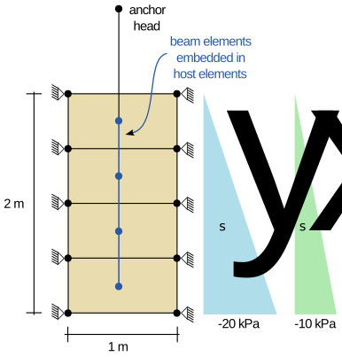
Figure 1: Model setup (not to scale).
Input files
Download the input file here
Closed-form pull-out capacity
The local capacity \(t_{cap} = A_s (c - \sigma_n \tan\varphi)\) is linear along each guest element (the host stresses at the guest nodes are interpolated with the linear guest shape functions), so 2-point Gauss integration is exact and
using \(\int \sigma_n \, \mathrm{d}s = -7.5\) kPa·m (trapezoidal over the nodal values, \(L = 1.5\) m).
Step 1: elastic pull-out (load controlled)
An upward load of \(F = 3.0\) kN is applied to the anchor head. The elastic response is independent of the capacity law: as in the constant-capacity benchmark,
The corresponding uniform traction \(k_t \, u_2 = 2.0\) kN/m stays below the smallest integration-point capacity (\(2.41\) kN/m, near the top of the anchor) - the interface is elastic everywhere and the step verifies that the Mohr-Coulomb law does not perturb the elastic regime. A comparison of the simulation results to the analytical solution is provided in Figure 2.
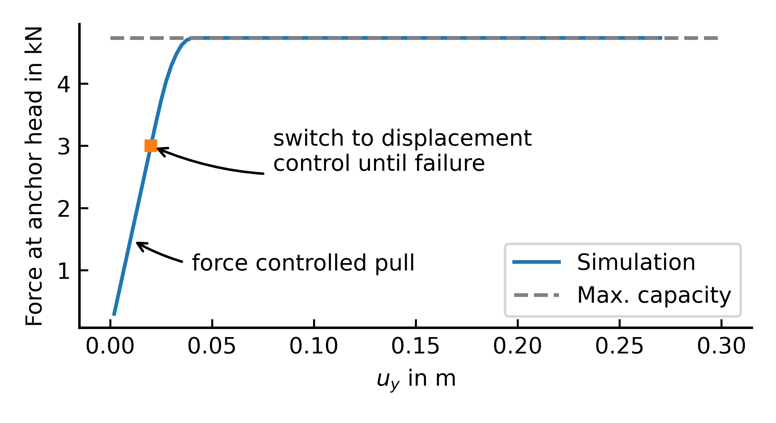
Figure 2: Simulation results vs. analytical solution.
Step 2: pull-out capacity (displacement controlled)
The anchor head displacement is increased to \(u_2 = 0.3\) m. All integration points reach their (depth-dependent) capacity and slide; the reaction force at the anchor head equals the closed-form pull-out capacity
reproduced by numgeo to machine precision, since the linear capacity distribution is integrated exactly by the 2-point Gauss rule.